4
Installation Instructions
Kit Part No. 5600079
5100079
Rev. 07/2006
TP 200-7302-00-CI-S
© Copyright 2006 Ferris Industries. All Rights Reserved.
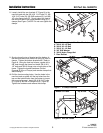
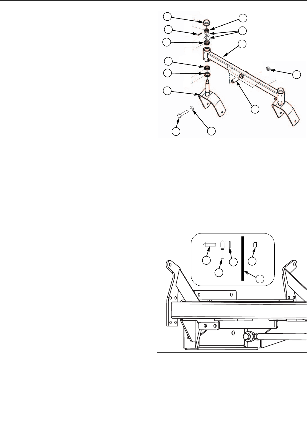
11. Remove the caster wheels yokes from the old front
end assembly. Refer to Figure 9, install the removed
yokes (G) and spacer (I) in to the new front end
assembly. If needed, clean and re-grease tapered
bearings before installation. Install the new caster
pivot frame (H) to the frame with the new 3/4”
hardware (J, K, L) provided.
21
22
23
23
Figure 9. Caster Pivot Frame Assembly
A. Cap
B. Slotted Nut
C. Cotter Pin
D. 3/4” SAE Washer
E. Bearing
F. Grease Seal
G. Caster Yoke
H. New Caster Pivot Frame
I. Spacer, .75 x 1.00 x 2.38
J. 3/4-16 x 6-1/2” Bolt
K. 3/4” SAE Washer
L. 3/4-16” Nylon Nut
A
B
C
E
E
F
G
I
H
D
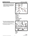
Figure 10. Reinstall the Puller Bar
A. Bolt
B. Ball Joint
C. Washer
D. Frame
E. Nut
12. Refer to Figure 10. Reinstall the mower deck puller
bar (front of the puller bar install on the inside of the
new front end). Install hardware removed previously.
Tighten the puller bar adjustment bolts (A, Figure 2).
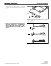
13. Reinstall the floor pan and the front shocks.
NOTE: Use the (3) 15” tie wraps to fasten the headlight
wire harness back to the frame.
J
K
L
B
A
C
E
D


