


MAINTENANCE
21
3. Hold adjusting flats and tighten nut.
4. Start unit and check auger. auger must not be engaged un-
less auger control is depressed.
5. With engine running, fully depress auger control, the auger
should engage and run normally.
WARNING: Always turn unit off, remove ignition key, and
disconnect the spark plug wire before making any
repairs or adjustments.
This snowthrower is equipped with two height adjust skids, secured
to the outside of the auger housing. These elevate the front of the
snowthrower.
When removing snow from a hard surface area such as a paved
driveway or walk, adjust the skids up to bring the front of the
snowthrower down.
When removing snow from rock or uneven construction, raise the
front of the snowthrower by moving the skids down. This will help to
prevent rocks and other debris from being picked up and thrown by
the augers.
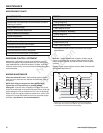
ADJUST SKID HEIGHT
To adjust skids, proceed as follows:
1. Place a block (equal to height from ground desired) under
scraper bar near but not under skid.
2. Loosen skid mounting nuts (A, Figure 14) and push the skid
down (B) until it touches the ground. Retighten mounting nuts.
3. Set skid on other side at same height.
NOTE: Make sure that snowthrower is set at same height on
both sides.
WARNING: Be certain to maintain proper ground
clearance for your particular area to be cleared.
Objects such as gravel, rocks, or other debris, if struck
by the impeller, may be thrown with sufficient force to
cause personal injury, property damage, or damage to
the snowthrower.
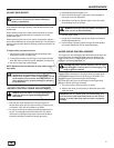
AUGER SHEAR PIN REPLACEMENT
The augers are secured to the auger shaft with special shear pins
that are designed to break if an object becomes lodged in the
auger housing. Use of a harder grade shear pin will reduce the
protection provided by the shear pin.
WARNING: Do not go near the discharge chute or auger
when the engine is running. Do not run the engine if any
cover or guard is removed.
Under most circumstances, if the auger strikes an object which
could cause damage to the unit, the shear pin will break. This
protects the gear box and other parts from damage.
The shear pins (A, Figure 16) are located on the auger shaft.
Replace a broken shear pin as follows.
1. Tap out the broken shear pin with a pin punch.
2. Install a new shear pin and cotter pin. Bend the ends of the
cotter pin down.
IMPORTANT: Do not replace shear pins with anything other
than the correct grade replacement shear pin. Use of bolts,
screws, or harder grade shear pins can result in equipment
damage.
AUGER CONTROL CABLE ADJUSTMENT
1. With the drive lever released, the hook (see Figure 15)
should barely touch the lever without raising it. There can be
a maximum 1/32” (0.8 mm) clearance as shown.
2. To adjust, loosen nut by holding the adjusting flats and turn-
ing nut. Turn adjustment flats and hold screw. The adjust-
ment screw is a phillips screw and the head can be held or
turned by inserting a screwdriver through the spring.
WARNING: Do not over-tighten, as this may lift the lever and
cause auger drive to be engaged without depressing the
Auger Control.
WARNING: The auger must stop within 5 seconds. If it
does not, see an authorized dealer.
6. Release auger control.
7. If auger does not operate properly, stop engine and recheck
drive linkage adjustments.
8. If drive linkage is properly adjusted, auger drive belt tension
may require adjustment. See an authorized dealer.
Not for
Reproduction