


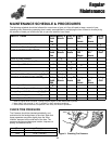

25
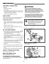
PTO CLUTCH ADJUSTMENT
Check the PTO clutch adjustment after the initial 25 hour
break-in period and then after every 100 hours of
operation. Also perform the following procedure if the
clutch is slipping or will not engage, or if a new clutch
has been installed.
• Remove key from ignition switch and disconnect
spark plug wires to prevent the possibility of
accidental starting while the PTO is being adjusted.
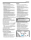
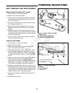
• See Figure 19. Note the position of the 3 adjustment
windows (A) in the side of the brake plate and the
nylock adjustment nuts (B).
•
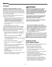
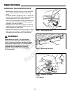
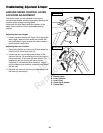
Insert a .016”-.018” (0,40-0,45mm) feeler gauge (C)
through each window, positioning the gauge between
the rotor face and the armature face as shown in
Figure 20.
• Alternately tighten the adjustment nuts (B, Figure 19)
until the rotor face and armature face just contacts
the gauge.
• Check the windows for an equal amount of tension
when the gauge is inserted and removed, and make
any necessary adjustments by tightening or
loosening the adjustment nuts.
NOTE: The actual air gap between the rotor and
armature may vary even after performing the adjustment
procedure. This is due to dimensional variations on
component parts, and is an acceptable condition.
•
Check the mower blade stopping time. The mower
blades and mower drive belt should come to a
complete stop within five seconds after the electric
PTO switch is turned off.
WARNING
To avoid serious injury, perform adjustments only
with engine stopped, key removed and unit on
level ground.
Blade Brake Check
Mower blades and mower drive belt should come to a
complete stop within five seconds after electric PTO
switch is turned off.
• With PTO disengaged, start the engine.
• Remove the mower deck guard and observe the
mower drive belt. Engage the PTO and wait several
seconds. Disengage the PTO and check the amount
of time it takes for the mower drive belt to stop.
• If the mower drive belt does not stop within five
seconds, perform the PTO Clutch Adjustment. If the
belt still does not stop within 5 seconds, see your
dealer.
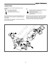
C
A
B
B
A
B
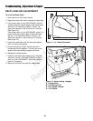
Figure 19. PTO Clutch Adjustment
A. Adjustment Window (Qty. 3, one shown)
B. Adjustment Nut
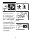
Figure 20. Adjust PTO Clutch
A. Window
B. Adjustment Nut
C. .016”-.018” (0,40-0,45mm) Feeler Gauge
B
Troubleshooting, Adjustment & Repair
Not for
Reproduction