


Adjustments
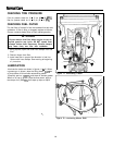
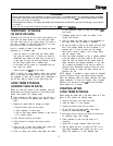
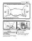
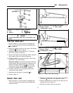
View is from right side of tractor
with rear wheel removed.
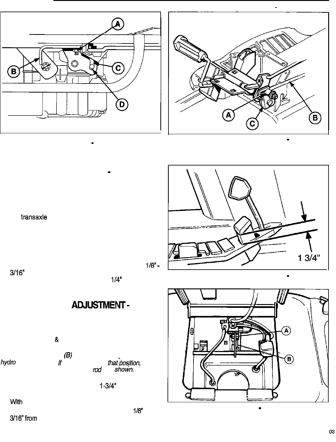
Figure 20. Neutral Adjustment
-
Hydro Model
A. Nut
C. Cam Slot
B. Neutral Adjustment Rod
D. Stop Pin
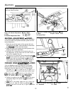
NEUTRAL ADJUSTMENT
-
HYDRO
If the tractor creeps forward or backward with the engine
running and both travel pedals released, perform the fol-
lowing adjustment:
1. Raise the rear of the tractor off the ground with suit-
able hoist or floor jack. Install jackstands underneath
the
transaxle and block the front wheels.
2. Start the engine and release the parking brake while
keeping seat switch depressed.
3. See figure 20. Loosen the nut (A) securing the neu-
tral adjustment rod (B). Move the rod until neutral is
found, then retighten the nut.
4. The stop pin (D, figure 20) should be positioned i/8”
-
3/16”
from the end of the cam slot (C, figure 20) as
shown when the front pedal edge is l/4” above the
frame (pedal fully depressed). If it is not, proceed to
the Forward Speed Adjustment procedure below.
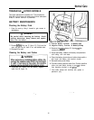
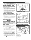
FORWARD SPEED
AtWSTMENT-
HYDRO
If the unit does not reach top speed with the forward
direction pedal fully depressed, perform the following
adjustment with the engine off and PTO disengaged.
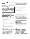
1. See figures 21 a
&
21 b. Loosen the nut (A, figure 21 a)
securing the control rod (B) to the hydro control lever.
NOTE: Hydro control rod (6) should be on the inside of the
hydm control lever(C).
If
the rod is not in thatbosirion,
remove the hardware, reposition the
md
as
shotin.
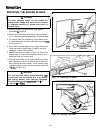
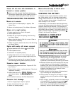
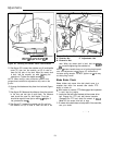
2. Position the pedal so the distance between the frame
and bottom edge of the pedal is i-3/4” as shown in
figure 21 b.
3.
With pedal in this position, tighten the nut (A, figure 21a).
4. The stop pin (D, figure 20) should be positioned
l/3”
to
306’from
the end of the cam slot (C, figure 20) as shown
Figure 21a. Forward Speed Adjustment
-
Hydro
A. Bolt
C.Hydro Control Lever
B. Control Rod
Figure 21 b. Forward Speed Adjustment
-
Hydro
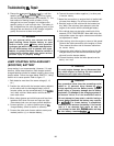
Figure 22. Neutral Adjustment
-
Gear Model
A. Hardware B. Shaft
22