


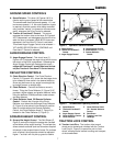
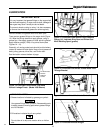
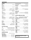
Figure 21. Belt Cover
Belt Cover
Screws
03
16
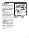
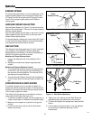
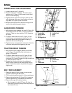
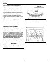
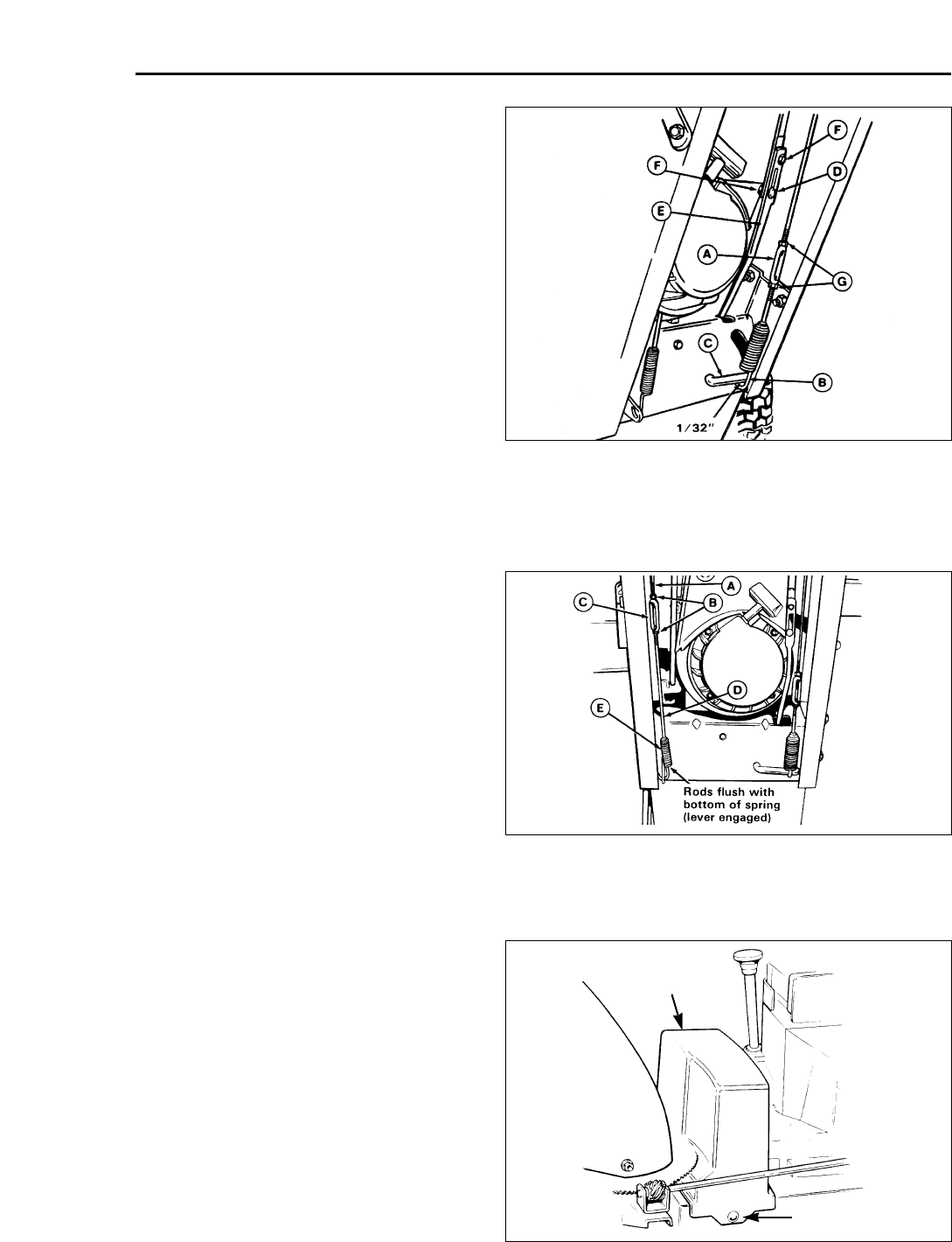
Figure 19. Speed Selector and Auger Drive Linkages
A. Turnbuckle E. Lower Rod
B. Spring Hook F. Nuts
C. Lever G. Nuts
D. Carriage Bolts
SPEED SELECTOR ADJUSTMENT
1. Loosen the two nuts (F, figure 19).
2. Place the shift lever in 5th gear. The lower speed
selector rod (E, Figure 19) will properly locate itself
due to an internal spring.
3. Tighten the two nuts. Do not lift up or down on rods
while tightening. Make sure the shoulders of the car-
riage bolts (D, Figure 19) are in the slots.
4. Always check traction drive tension and auger drive
tension after adjusting speed selector.
AUGER DRIVE TENSION
1. With the drive lever released, the hook (B, Figure 19)
should barely touch the lever (C, Figure 19) without
raising it. There can be a maximum 1/32” clearance
as shown.
2. To adjust, loosen the two nuts (G, Figure 19) and
hold the lower rod to keep from rotating. Turn the
turnbuckle toward the right to lower the spring, or
toward the left to raise the spring.
3. Tighten the two nuts against the turnbuckle. Hold the
turnbuckle with pliers while tightening the nuts.
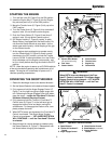
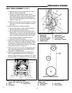
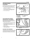
TRACTION DRIVE TENSION
1. With the drive lever engaged, bottom end of lower
rod (D, Figure 20) should be flush with bottom of
spring (E, Figure 20).
2. To adjust, loosen the two nuts, (B, Figure 20) and
hold the lower rod to keep from rotating. Turn the
turnbuckle (C, Figure 20) toward the right to lower rod
or toward the left to raise rod.
3. Engage the drive lever to check the adjustment.
When correct, tighten the two nuts against the turn-
buckle. Hold the turnbuckle with pliers while tighten-
ing the nuts.
BELT REPLACEMENT
1. Rotate the spout full right. Loosen the two screws
(Figure 21) securing the belt cover.
2. Tilt the cover forward and work it off the snowthrower.
3. Remove the belt guides (B, Figure 22) by loosening
the two capscrews (A), lockwashers and washers.
4. Remove the auger drive belt as follows:
a. Slip the auger drive belt (D, Figure 22) from the
idler pulley by pushing it away from the pulley and
then toward the rear.
Service
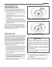
Figure 20. Drive Tension Adjustment
A. Upper Rod D. Lower Rod
B. Nuts E. Spring
C. Turnbuckle