


9
The unit should now be completely assembled and ready for use
with a blade.
IMPORTANT!
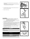
Discard blades that are bent, warped, cracked, broken or damaged in any way.
Use a sharp blade. A dull blade is more likely to snag and thrust.
C
J
I
F
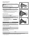
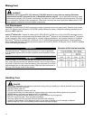
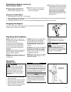
d. Remove three screws holding shield plate (E) and plastic shield (C) to
gear housing.
e. Retain line head (B), adapter plate (D), shield plate, and plastic shield for
conversion back to nylon line head operation.
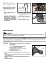
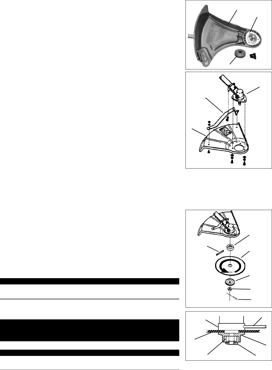
Install Blade
Tools Required: 4 mm hex key wrench (locking tool), 17 mm wrench, Pliers
Parts Required: Adapter plate w/25 mm diameter pilot, lower blade
mounting plate, 10 mm hex nut w/L.H. thread, 2 mm x 25 mm
cotter pin, blade w/25 mm arbor diameter.
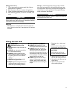
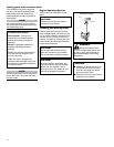
1. Install adapter plate (D) on splined PTO shaft, pilot side down. Blade installa-
tion requires Adapter Plate (D) with 25 mm pilot.
2. Install Blade (K) on adapter plate pilot. Blades must be installed so that rota-
tion arrow on blade matches rotation of unit: teeth toward direction of rotation
(See debris shield decal). Secure blade with Lower Plate (H), and 10 mm
L.H. nut (G). Turn nut counter-clockwise on PTO shaft to tighten.
3. Align hole in adapter plate with notch in gear housing, and insert Locking Tool
(A) to prevent splined shaft from turning. Arrow on gear housing points to
notch. Tighten 10 mm nut securely.
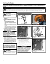
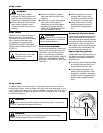
4. Insert Cotter Pin (L) in hole in PTO shaft, and bend pin legs around shaft
counterclockwise to retain 10 mm nut.
IMPORTANT!
Never reuse a cotter pin - install a new cotter pin each time a blade is installed or
replaced.
5. Remove locking tool.
D
25
A
K
G
L
H
D
K
H
G
L
A
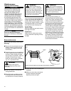
2. Loosely attach bracket (I) to shield (J) and attach shield to bottom of gear
housing (F) with hardware provided.
3. Tighten all shield hardware.
E
D