


8
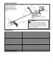
Assembly (continued)
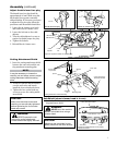
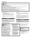
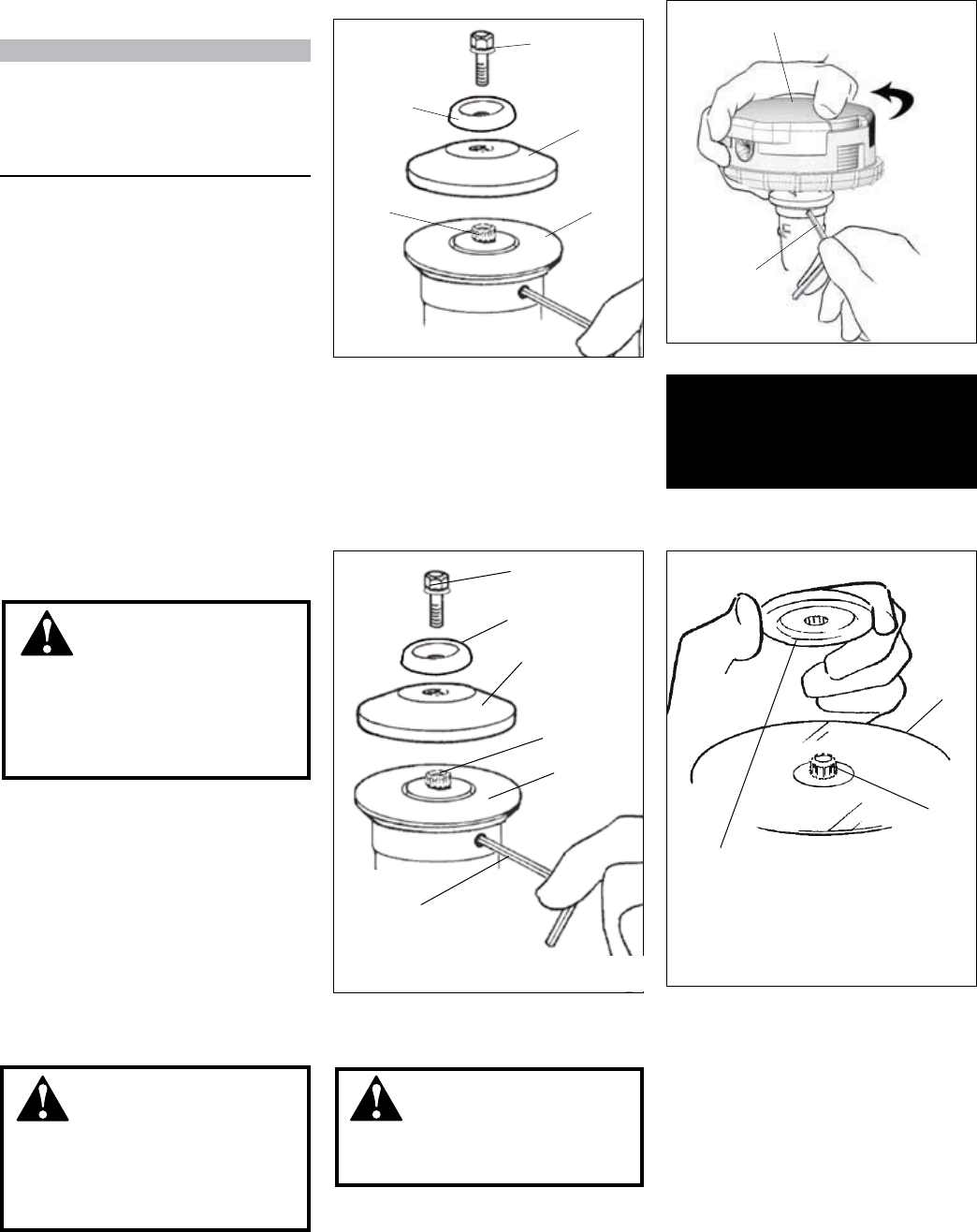
NOTE:
This unit is shipped with Holder A,
Holder B, shaft bolt, and bolt guard
installed. The shaft bolt is a LEFT-
HAND thread. Remove it by turning
CLOCKWISE!
With the gearcase output shaft facing 1.
up, rotate the gearshaft and Holder A
until the hole in Holder A aligns with
the matching hole in the gearcase
flange, and then lock the holder to
the gearcase by inserting the long
end of the hex wrench through both
holes.
Using the combination spark plug/2.
screwdriver wrench, remove the
shaft bolt, and bolt guard. (The bolt
guard and shaft bolt are not used
with a trimmer head).
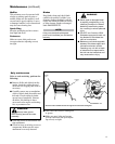
Installing a Trimmer Head
Shaft Bolt
Bolt Guard
Gear Shaft
Hex Wrench
Holder B
Holder A
Hand-tighten Trimmer Head (counter-
clockwise to install)
Using the hex wrench to secure 3.
Holder A, install and hand-tighten
the trimmer head (counter-clockwise
to install).
Remove the hex wrench from the 4.
gearcase and holder.
This unit is now completely
assembled and ready to use as
a trimmer.
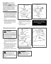
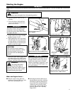
Turn the unit upside down so the 1.
gear case output shaft is facing UP
and remove the shaft bolt, bolt guard
and holder B from the gear case
shaft.
Align the hole in blade holder A with 2.
the matching hole in the gear case
flange and then temporarily lock
the output shaft by inserting a hex
wrench through both holes.
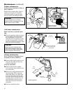
Fit the blade over the flange on holder 3.
A.
Shaft Bolt
Bolt Guard
Holder B
Gear Shaft
Holder A
Hex wrench
Temporarily lock the output shaft by
inserting a hex wrench through both holes
Install blade holder B on the output shaft.
Blade
Blade Holder B
Output
Shaft
WARNING!
The blade must t at
against the holder ange. The
blade mounting hole must be cen-
tered over the raised boss on blade
Holder A.
WARNING!
Holder B must t ush
against the blade and the splines
engaged to the output shaft.
WARNING!
Do not attach any blade to
a unit without proper installation of
all required parts. Failure to use the
proper parts can cause the blade to
y off and seriously injure the oper-
ator and/or bystanders.
Install blade holder B on the output 4.
shaft.
Installing Brushcutter Blade