


7
23106
23105
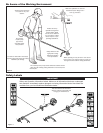
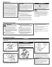
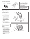
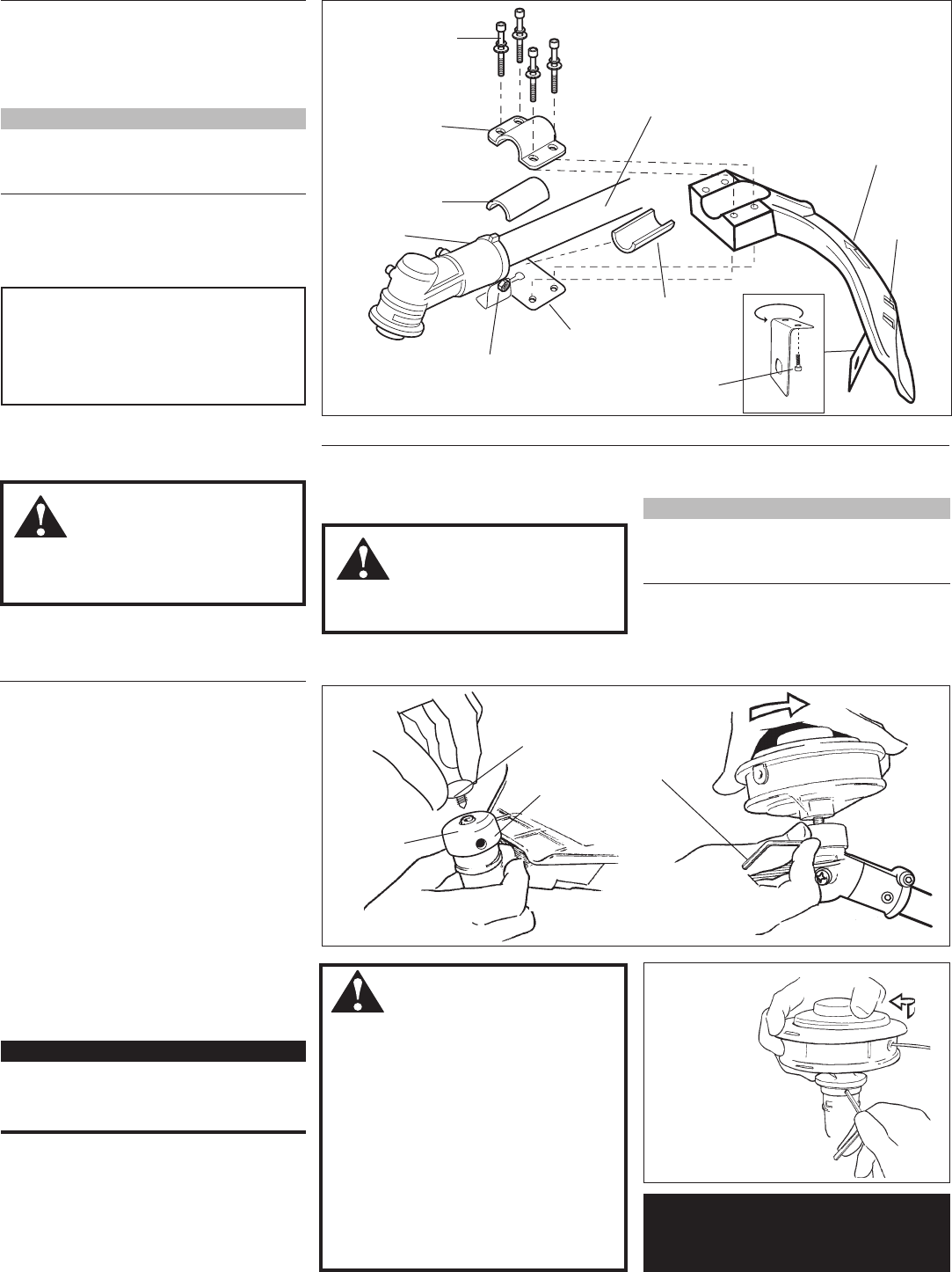
Figure 9
Cutting Attach-
ment Shield
Outer
Tube
Socket-
Head Cap
Screw
Bracket
Shim
Clamp Screw
Shim
Retaining
Nut
Cutting
Attachment
Mounting
Plate
Line Cutter
Figure 9A
Hex
Screws
Nuts
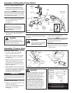
Install the Cutting Attachment Shield.
1. Insert the cutting attachment shield
between the outer tube and the cutting
attachment mounting plate. See Figure 9.
WARNING!
NEVER operate the unit
without the cutting attachment shield
installed and tightly secured!
CAUTION!
Make sure the clamp screw and
retaining nut are securely tightened
before tightening the four socket-
head cap screws.
NOTE:
It may be necessary to loosen the retaining
nut and clamp screw to adjust cutting attach-
ment shield mounting plate.
2. Fit the two shims and the bracket over
the outer tube and loosely install the
four socket-head screws.
See Figure 9.
WARNING!
The line cutter is very sharp.
Wear gloves to protect your
hands when handling.
To Change Position of Line Cutter
1. Remove the 2 hex screws with a 4mm
hex wrench. See Figure 9A.
NOTE:
Be careful to not lose the 2 nuts in the cut-
ting attachment shield, they are
not captured.
The line cutter can be positioned in
2 positions to obtain different line length
for cutting.
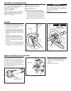
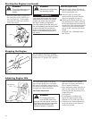
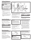
Install the Trimmer Head.
1. Turn the trimmer over so that the
gearcase output shaft faces UP.
2. Remove and discard the black plastic
retaining plug from the output shaft.
See Figure 10.
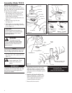
3. Rotate the holder until the hole in the
holder aligns with the notch on the
gearcase. Use the long end of the hex
wrench to lock the holder and output
shaft. See Figure 10.
4. While holding the hex wrench, thread
the trimmer head onto the output shaft,
turning counter-clockwise. Using hand
pressure only, tighten the trimmer
head firmly on the output shaft.
IMPORTANT!
The trimmer head has a left-hand thread.
For removal turn the trimmer head clock-
wise.
5. Remove the hex wrench.
6. Adjust the trimmer line length to reach
no further than the line
cutter on the cutting attachment shield.
Trim to the correct length
if necessary.
Assembly: Trimmer Head
Figure 10
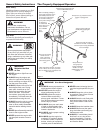
WARNING!
A standard grass trimmer with a loop
handle should NEVER be operated
with blade-type attachments. For
blade use the trimmer must be tted
with a bicycle-type handlebar or
loop handle with a barrier bar that
is located in front of the operator to
reduce the risk of the operator from
coming in contact with the cutting at-
tachment (per ANSI B175.3). When
using a blade, the unit must also be
equipped with a harness or strap.
23107
The unit should now be
completely assembled and ready for
use with a trimmer head.
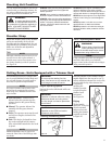
Holder
Output
shaft
Retaining
Plug
23108
Figure 11
Hex Wrench
Assembly: Cutting Attachment Shield
3. Tighten the four socket-head cap
screws to secure the cutting attach-
ment shield.
2. Rotate line cutter. See Figure 9A.
3. Reinstall the two hex screws and tighten
them securely.
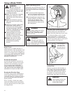
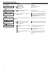
To install a
trimmer head
onto a T231X,
first remove the
shaft bolt, bolt
guard and
safety clip
(see the next
page).