6
IMPORTANT!
The terms “left”, “left-hand”, and “LH”;
“right”, “right-hand”, and “RH”; “front” and
“rear” refer to directions as viewed by the
operator during normal operation.
WARNING!
Do not make unauthorized
modications or alterations to your
unit or its components.
Before assembling, make sure you have all the components required for a
complete unit:
Outer Tube/Mainshaft Assembly ■
Tiller/Cultivator Tool Assembly ■
Kit containing hardware, owner/operator's manual, and a 5 mm hex key. ■
Carefully inspect all components for damage.
Assembly
Prior to assembly
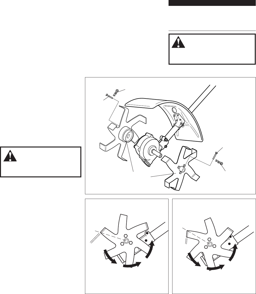
Tine Installation and Orientation
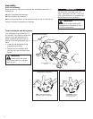
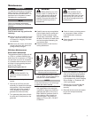
Tine installation directly affects the Til-
ler/Cultivator Tool’s ability to break new
ground. Using the illustrations as a
guide, determine the correct tine ori-
entation for the tilling/cultivating job at
hand:
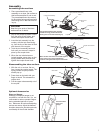
Install the tine assemblies to the 1.
gearcase output shafts.
Secure each tine assembly with 2.
one clevis pin and one hitch pin as
shown.
WARNING!
Always switch the engine
OFF before working on the gear-
case or tines!
Hitch Pin
Tine Assemblies (hub
faces in)
Clevis Pin
MCLT23006
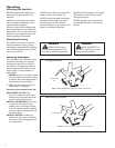
Tiller Leading edge out for
aggressive action in hard soils.
Tilling/Digging in Hard Soil
Leading
Edge
Out
MCLT23007
Weeding/Cultivating in Softer Soil
Cultivator Leading
edge in for weeding or
turning softer soils.
Leading
Edge In
Install the tine assemblies
Hitch Pin
Clevis Pin


