


6
WARNING!
Do not make unauthorized modications or alterations to this machine or any of its components or accessories.
Unit Description
IMPORTANT!
The terms “left,” “left-hand,” and “LH”; “right,” “right-hand,” and “RH” ; “front” and “rear” refer to directions as
viewed by the operator during normal operation of this product.
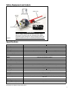
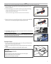
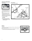
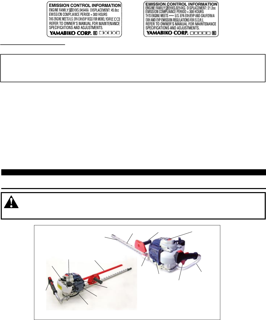
Familiarize yourself with your machine and its various components. Understanding your machine helps ensure top performance,
long service life, and safer operation.
Air Cleaner
Cover
Fuel Tank
Protector
Gearcase
Throttle Trigger
Support Handle
Choke
Throttle Handle
ON-OFF
Switch
Guide Bar
Cutter
Fuel Cap
Recoil
Starter
Blade
Cover
Figure 3
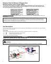
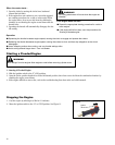
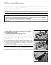
Prior to use
Before using this product, please make sure you have all the components required for a complete unit:
n1. Engine assembly and gearcase/cutter assembly
n2. Combination spark plug/13mm wrench
Carefully inspect all components for damage.
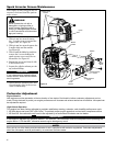
An Emission Control Label is located on the unit. (This is an EXAMPLE ONLY; information on label varies by en-
gine FAMILY).
PRODUCT EMISSION DURABILITY (EMISSION COMPLIANCE PERIOD)
The 300 hour emission compliance period is the time span selected by the manufacturer certifying the engine
emissions output meets applicable emissions regulations, provided that approved maintenance procedures are
followed as listed in the Maintenance Section of this manual.
Emission Control (Exhaust & Evaporative)
EPA 2010 and Later and/or C.A.R.B. TIER III
The emission control system for the engine is EM/TWC (Engine Modication and 3-way Catalyst) and for
the fuel tank the Control System is EVAP (Evaporative Emissions) or N (for nylon tank). Evaporative emis-
sion may be applicable to California models only.
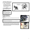
Mufer