17
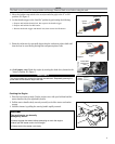
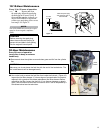
Figure 25
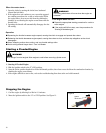
Long Term Storage
Whenever the unit will not be used for 30 days or longer, use the following procedures to prepare it for storage:
Clean external parts thoroughly.
■
Drain all the fuel from the fuel tank. ■
IMPORTANT!
Stored fuel ages. Do not mix more fuel than you expect to use in thirty (30) days, ninety (90) days when a fuel stabilizer is
added.
CAUTION!
Gasoline stored in the carburetor for extended periods can cause hard starting and could also lead to increased service
and maintenance cost.
Remove the remaining fuel from the fuel lines and carburetor.
■
Prime the primer bulb until no more fuel is passing through.1.
Start and run the engine until it stops running.2.
Repeat steps 1 and 2 until the engine will no longer start.3.
Remove the spark plug and pour about 1/4 ounce of engine oil into the cylinder through the spark plug hole. Slowly pull
■
the recoil starter 2 or 3 times so oil will evenly coat the interior of the engine. Reinstall the spark plug.
Before storing the unit, repair or replace any worn or damaged parts.
■
Remove the air cleaner element from the carburetor and clean it thoroughly with soap and water. Let dry and reassemble ■
the element.
Store the unit in a clean, dust-free area.
■
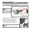
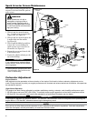
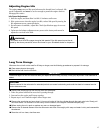
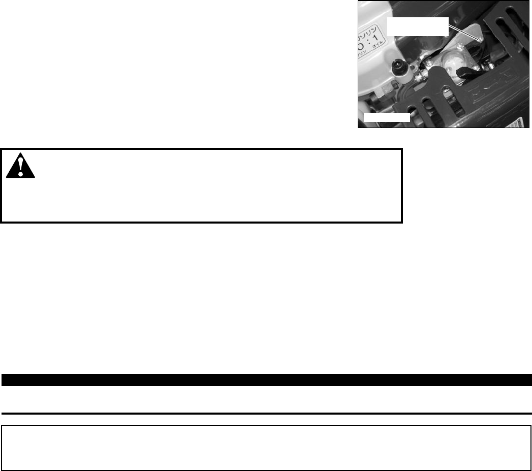
The engine must return to idle speed whenever the throttle lever is released. Idle
speed is adjustable, and must be set low enough to permit the engine clutch to
disengage the cutters.
Adjusting Engine Idle
WARNING!
The cutters must NEVER engage at engine idle speeds! If the idle speed cannot be ad-
justed by the above procedure, return the trimmer to your Shindaiwa dealer for inspection.
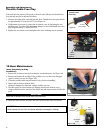
Idle Speed Adjustment
Start the engine, and then allow it to idle 2–3 minutes until warm.1.
If the cutters move when the engine is at idle, reduce idle speed by turning the 2.
idle adjustment screw counterclockwise.
If a tachometer is available, adjust idle. Check Specifications page for correct 3.
idle speed
Carburetor fuel mixture adjustments are preset at the factory and cannot be 4.
adjusted or serviced in the field.
Idle Adjustment
Screw
Figure 10


