


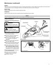
14
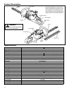
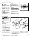
Mufer
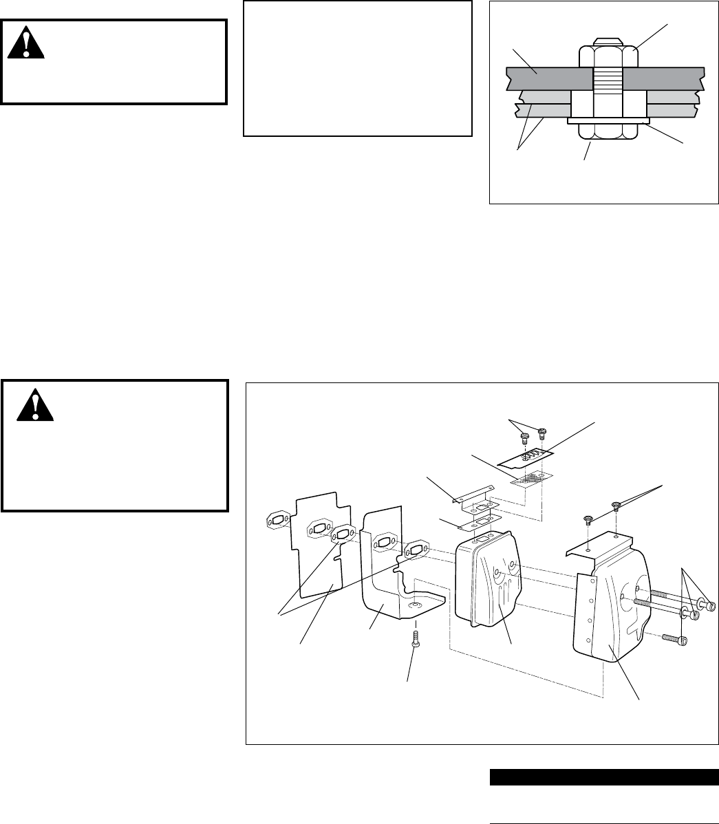
gasket
Mufer
Spark arrester screen
Top tail plate
Lower tail plate
Mufer gasket bolt
Mufer
cover
Mufer
cover bolts
Gasket plate
Plate
Mufer cover
screws
Mufer plate screws
Gaskets
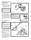
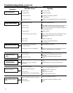
135 - hour maintenance
WARNING!
Never operate the unit with
a damage or missing mufer or spark
arrester! Operating with a missing
or damaged spark arrester is a re
hazard and could also damage your
hearing.
Maintenance (continued)
If the engine becomes sluggish and
low on power, check and clean the
spark arrester screen.
Loosen the knob of the spark plug 1.
cover and remove the cover.
Remove the spark plug lead from 2.
the spark plug.
Loosen the four 5 mm bolts located 3.
at the top of the recoil starter hous-
ing and remove the cover.
Loosen the 5 mm bolt located at the 4.
top of the cylinder cover and two
4 mm bolts located at the bottom
of the cylinder cover and remove
cover.
Loosen three 5 mm mufer cover 5.
bolts and remove the mufer cover.
Remove mufer gasket bolt.6.
Loosen two 4 mm screws from the 7.
mufer cover.
Remove two 4 mm screws from the 8.
top tail plate and remove tail plate.
Remove the spark arrester screen 9.
and clean with a stiff bristle brush.
Remove the mufer from the engine 10.
and inspect the cylinder exhaust
port for carbon buildup.
Reassemble the mufer in the 11.
reverse order of disassembly
IMPORTANT!
If you note excessive carbon buildup,
consult your servicing dealer.
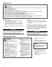
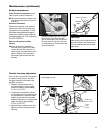
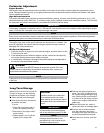
Locknut
Guide Bar
Cutter
Blades
Shoulder Bolt
Washer
(should turn
freely)
Adjusting cutter blades
Cutting performance of your machine
depends a great deal on proper cutter
blade adjustment. Properly adjusted
blades will oscillate freely yet help pre-
vent binding of cut material between
blades. Adjust blades as follows:
Loosen all blade locknuts at least 1.
one full turn.
Tighten each blade shoulder bolt 2.
rmly, and then loosen the shoulder
bolts 1/4 to 1/2 turn.
Cutter blade adjustment
Working from the gearcase end, 3.
lock each bolt in place by rmly
tightening its locknut while prevent-
ing the shoulder bolt from turning.
When shoulder bolt adjustment is cor-
rect, there should be a gap of 0.25–
0.50 mm between the cutter blades
and the at washers, and the at
washer beneath each bolt head should
turn freely.
WARNING!
The cutter blades are very
sharp! Always wear gloves when
working around the cutter assembly.
CAUTION!
Operating the trimmer with worn
or improperly adjusted cutters will
reduce cutter performance and may
also damage your machine. Never
operate the machine with damaged or
worn cutters.