


7
Assembly
Prior To Assembly
IMPORTANT!
The terms “left”, “left-hand”, and
“LH”; “right”, “right-hand”, and “RH”;
“front” and “rear” refer to directions as
viewed by the operator during normal
operation.
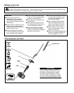
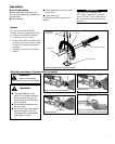
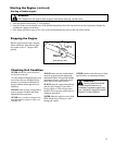
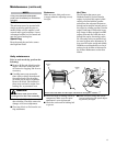
Outer Tube
Socket-head
Capscrews
Handle
Mounting Bracket
Throttle Assembly
Position the handle on the outer tube as shown
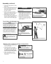
Handle
This unit comes with the handle
installed. It can be re-adjusted for opera-
tor comfort in the following manner.
Loosen the four hex screws.1.
Rotate/slide handle assembly to best 2.
position for operator comfort, usually
25 cm (10 in.) ahead of the throttle
assembly.
Tighten hex screws in a crisscross 3.
manner.
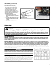
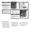
Before assembling, make sure you
have all the components required for a
complete unit:
Unit assembly
■
This manual and tool kit for routine ■
maintenance.
Cutter blade cover
■
Carefully inspect all components for
damage.
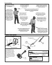
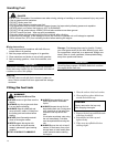
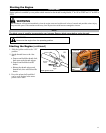
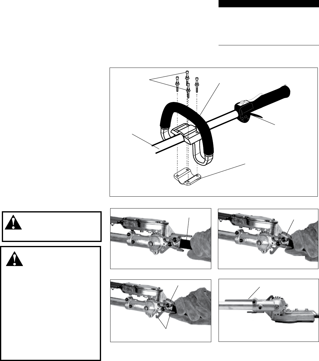
Adjusting the Hedge Trimmer Cutter Assembly
WARNING!
WARNING!
Never run the engine
when adjusting the cutter assembly.
Latch Release
Grasp the outer tube near the handle
Adjustment Lever
Adjustment Lever
Pivot the cutter assembly using the
adjustment lever...
Press the latch lock
Make sure the latch lock and the latch release
return securely to the straight ahead position
Latch Lock
Latch Lock
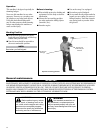
The cutter blades are very ■
sharp. Do not grasp the blades
with your hands. Always use
gloves when working near the
cutter assembly.
Do not allow the blades to con-
■
tact your body.
Do not touch the cutter blades
■
when the engine is running.
The blades can oscillate even
if the engine is idling.