


7
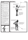
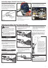
Adjusting the Hedge Trimmer Cutter Assembly
WARNING!
n The cutter blades are very sharp.
Do not grasp the blades with your
hands. Do not brush the blades
against your body.
n Never run the engine nor operate
the articulated hedge trimmer when
the cutter assembly is in the stor-
age/transport position.
IMPORTANT!
Always use gloves when working near
the cutter assembly.
Position the hedge trimmer on a flat, level
surface with the engine resting on the fuel
tank guard. Make sure the scabbard is in
place on the blade.
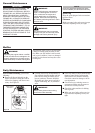
1. With your right hand, grasp the handle,
located immediately behind the hand
guard. With your left hand, grip the ad-
justment lever on the cutter assembly.
See Figure 13.
2. With the index finger of your left hand,
press the latch release. With your left
thumb, press the latch lock.
See Figure 14.
Figure 13
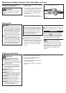
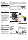
3. While holding the latch lock down, pivot
the cutter assembly using the adjust-
ment lever until it is straight with the
outer tube (pivot 180°).
See Figure 15.
IMPORTANT!
The latch lock provides an interlock to
help prevent inadvertent depression of
the latch release.
Figure 15
Adjustment Lever
Adjustment Lever
4. Release the latch lock and the latch
release. Make sure the latch lock and
the latch release return securely to a
locking position.
5. Remove the scabbard from the cutter
blade. The engine now may be started.
Figure 14
Latch Release
Latch Lock
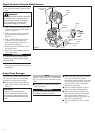
3/16-1/4 inch (4-6
mm) Throttle Free
play
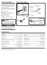
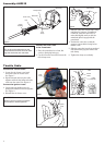
Assembly: Adjust Throttle Lever Free Play
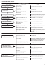
1. Loosen the air cleaner cover knob
and remove the air cleaner cover.
See Figure 11.
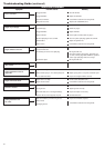
2. Loosen the lock nut on the cable ad-
juster. See Figure 12.
Cable
Adjuster
Figure 11
Figure 12
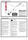
The throttle lever free play should be ap-
proximately 3/16-1/4 inch (4-6 mm). See
Figure 10. Make sure that the throttle
lever operates smoothly without binding.
If it becomes necessary to adjust the lever
free play, follow the procedures and illus-
trations that follow.
Figure 10
3. Turn the cable adjuster in or out as
required to obtain proper free play
3/16-1/4 inch (4-6 mm). See Figure 12.
4. Tighten the locknut.
Lock
Nut
5. Reinstall the air cleaner cover.
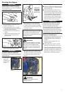
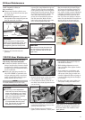
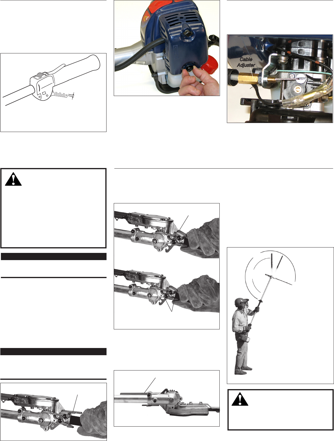
Figure 16
The cutter assembly
can be adjusted to 10
different positions rang-
ing from 120° to 270°
from the outer tube as
shown in Figure 14.
Refer to the steps on the
previous page for adjust-
ment procedures. Al-
ways make sure the lock
latch is securely locked
after each adjustment.
Various blade
positions possible
270°
120°
Adjusting the Hedge Trimmer Cut-
ter Assembly for Desired Cutting
Angles
WARNING!
Do not touch the cutter blades when
the engine is running. The blades can
oscillate even if the engine is idling.