


8
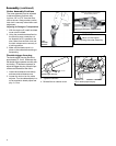
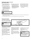
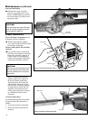
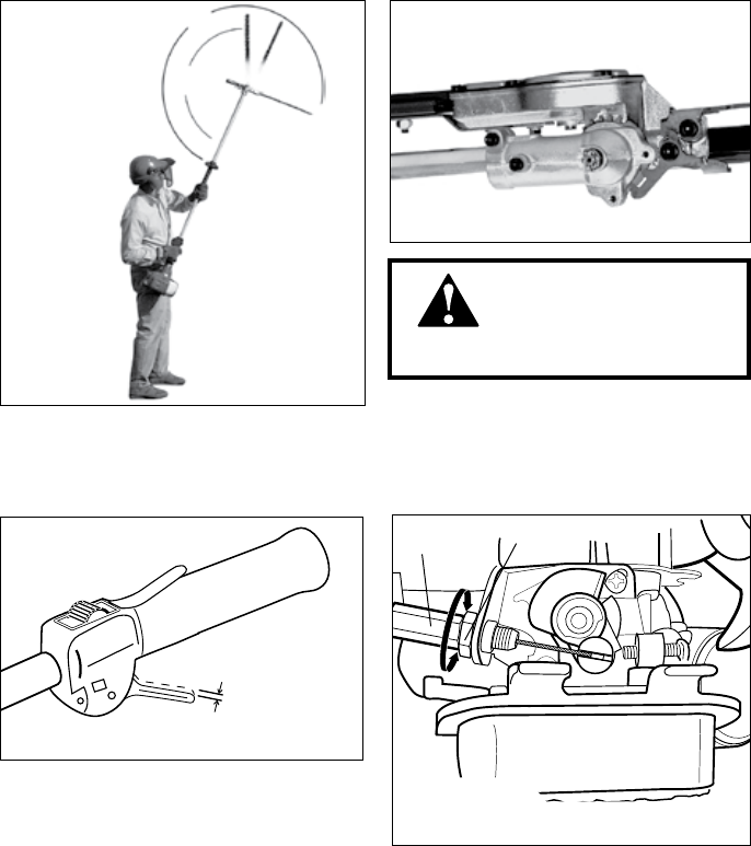
Cable
Adjuster
Rotate cable
adjuster in or
out to obtrain proper free play
Lock
Nut
4 - 6 mm
Throttle trigger free play
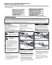
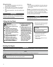
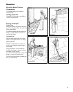
The cutter assembly can be adjusted
to eleven different positions rang-
ing from 120° to 270° from the outer
tube as shown. Always make sure the
latch lock is securely locked after each
adjustment.
Cutter Assembly Positions
270°
120°
Various blade
positions
possible
Cutter
Assembly
Positions
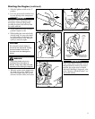
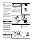
Assembly (continued)
With the engine off, install the blade 1.
cover onto the blade.
Using the procedures described on 2.
the previous page, rotate the cut-
ter assembly so it is parallel to the
tube. Make sure the latch lock and
the latch release return securely to
a locking position.
Make sure the blade cover is in 3.
place on the cutters before storing or
transporting.
Gearcase rotated to the storage/
transportation position
Adjusting for Storage or Transportation
WARNING!
Never run the engine
when adjusting the cutter assembly.
Adjusting for Storage or Transportation
The throttle trigger free play should be
approximately 4 - 6 mm. Make sure that
the throttle trigger operates smoothly with-
out binding. If it becomes necessary to
adjust the trigger free play, follow the pro-
cedures and illustrations that follow.
Loosen the air cleaner cover knob(s) 1.
and remove the air cleaner cover.
Loosen the lock nut on the cable 2.
adjuster. Turn the cable adjuster in or
out as required to obtain proper free
play 4 - 6 mm.
Tighten the locknut.3.
Reinstall the air cleaner cover.4.
Throttle trigger free play