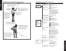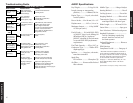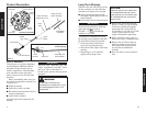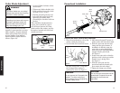
Starting A Cold Engine – Restarting After Refueling
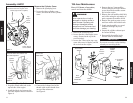
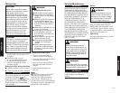
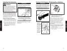
Figure 16
IMPORTANT!
Engine ignition is controlled by a two-
position START-STOP switch mounted
on the throttle body, typically labelled
“I” for START and “O” for STOP.
A
H231_22
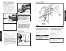
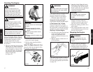
Primer
Bulb
Return Tube
Figure 17
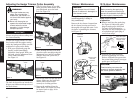
Choke
Lever
Closed
3. Choke the engine by moving the
choke lever up to the “closed”
position. See Figure 18.
Before starting the engine, make sure
the cutter assembly is in the cutting
position (extended). Refer to page 13
for adjustment procedures. Never
start the engine with the cutter
assembly in the storage/transporta-
tion position.
Figure 18
AH231_23
16
2. Prime the
engine by
depressing
the carbure-
tor primer
bulb four or
five times.
See Figure
17. You
should be
able to see
fuel inside
the bulb.
Control Positions (warm engine)
1. Slide the ignition switch to the “I”
(START) position.
2. Move the choke lever down to the
“open” position.
1. Slide the ignition switch to the “I”
(START) position. See Figure 16.
OPERATION
WARNING!
The cutter attachment must never
oscillate at engine idle speed. If
the idle speed cannot be adjusted
by the procedures described here,
return the trimmer to your
Shindaiwa dealer for inspection.
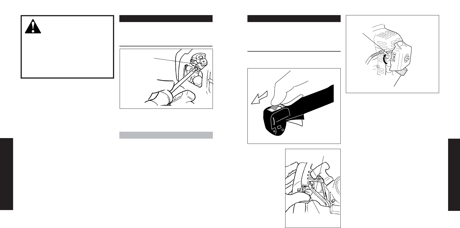
Adjusting The Carburetor
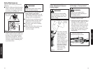
Idle Adjusting
Screw
Figure 23
AH231_28
19
NOTE
This model is equipped with an EPA
approved carburetor with no mixture
adjustment.
IMPORTANT!
Use a tachometer, if one is available, to
set engine idle. Standard idle speed is:
2,750 (±250) rpm (min
-1
).
The engine must return to idle speed
whenever the throttle trigger is released.
Idle speed is adjustable and must be set
low enough to permit the engine clutch
to disengage the cutter attachment when
throttle trigger is released.
Check and Adjust Idle Speed
1. Start the engine and allow it to idle two
or three minutes, or until it warms up.
2. If the cutter attachment rotates at
engine idle, reduce idle speed by
turning the idle adjusting screw
counter-clockwise as necessary.
See Figure 23.
3. If the engine is stalling and won’t
idle, increase idle speed by turning
the idle adjustment screw clockwise.
OPERATION


