


6
6
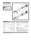
26104
26103
26101
26102
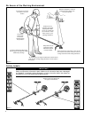
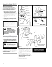
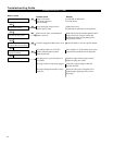
3/16-1/4 inch (4-6 mm)
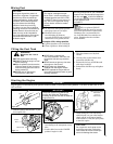
Throttle Freeplay
Adjust Throttle Lever Free Play
1. Loosen the throttle cable lock nut and
rotate the cable adjuster in or out to
achive proper free play of 3/16-1/4
inch(4-6 mm). See Figure 8.
2. Retighten the locknut.
Assembly and Adjustments
Figure 8
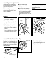
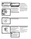
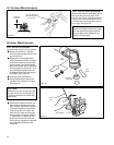
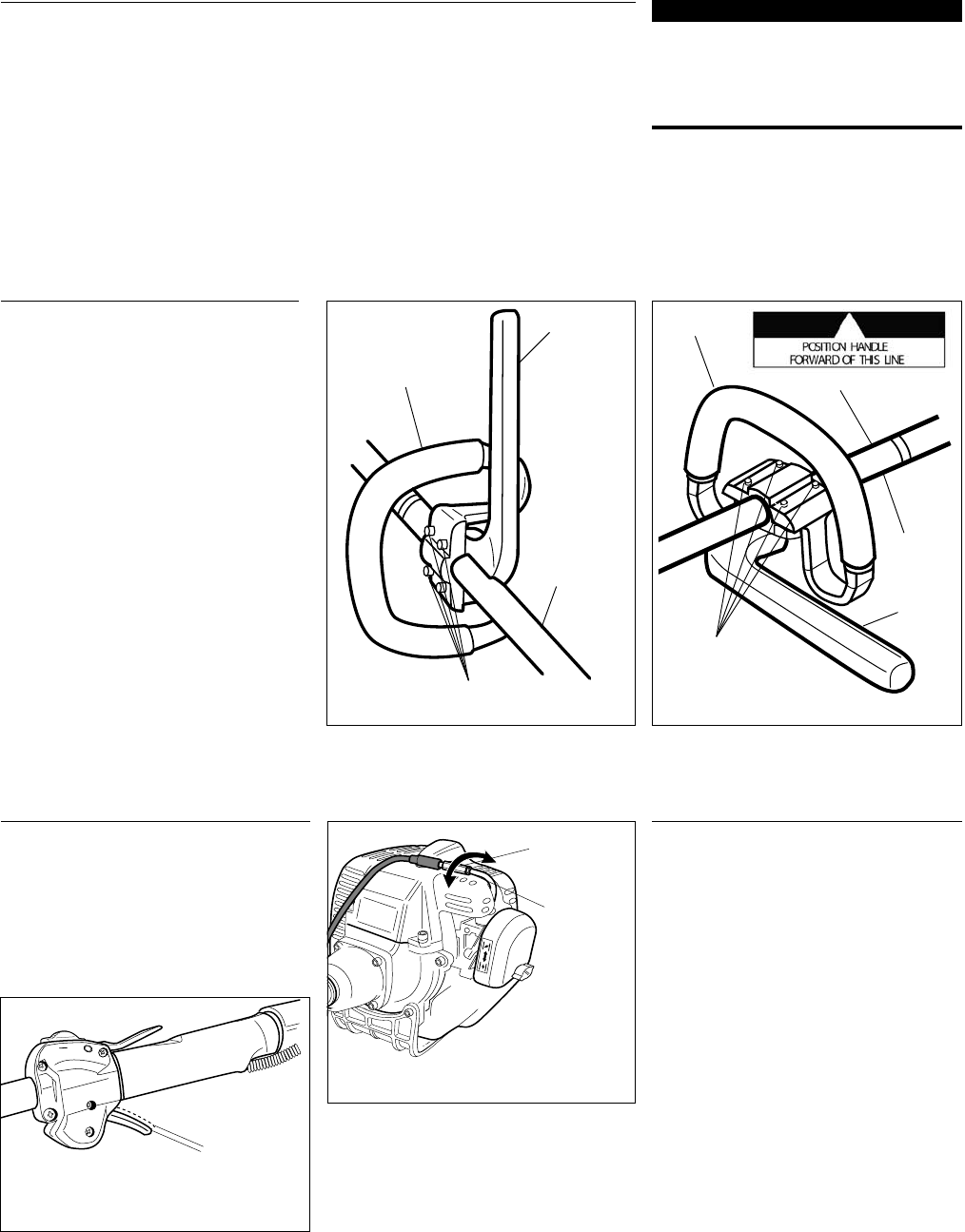
Figure 5
Handle
Outer
Tube
Handle
Handle Positioning Label
4 Socket-head Cap-
screws
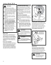
The throttle lever free play should be ap-
proxiamtely 3/16-1/4 inch(4-6 mm). See
Figure 7. Make sure that the throttle lever
operates smoothly without binding.
If it becomes necessary to adjust the lever
freeplay, follow the procedures and illus-
trations that follow.
Figure 7
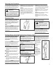
Handle
Outer
Tube
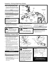
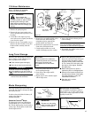
Figure 6
4 Socket-head Cap-
screws
Barrier
Bar
Barrier
Bar
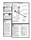
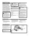
This unit comes fully assembled with
the exception of the cutting attachment
shield and cutting attachment.
Prior to Assembly
Before assembling, make sure you have
all the components required for a com-
plete unit and inspect unit and compo-
nents for any damage.
IMPORTANT!
The terms “left”, “left-hand”, and “LH”;
“right”, “right-hand”, and “RH”; “front” and
“rear” refer to directions as viewed by the
operator during normal
operation.
n
Engine and shaft assembly
n Cutting attachment shield
n Cutting attachment
n Kit containing cutting attachment
shield mounting bracket and hardware,
this owner's/operator's manual and
tool kit for routine maintenance. Tool
kits vary by model and may include a
hex wrench set, a spark plug/screw-
driver combination wrench, and a span-
ner.
Throttle Cable
Adjuster
Lock Nut
1. The handle is attached to the outer
tube at the factory and positioned in an
off-set position. See Figure 5.
2. Loosen the 4 socket-head cap screws
on the handle and rotate the handle
until the barrier bar is positioned hori-
zontally on the left side of the unit. See
Figure 6.
3. Position the handle forward of the
Handle Positioning Label at the best
position for operator comfort (usually
about 10 inches ahead of the throttle
housing).
4. Secure the handle by alternately tight-
ening the four socket-head cap screws
in a diagonal or “criss-cross” fashion.