


6
22010A
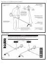
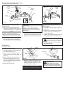
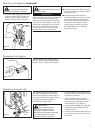
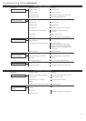
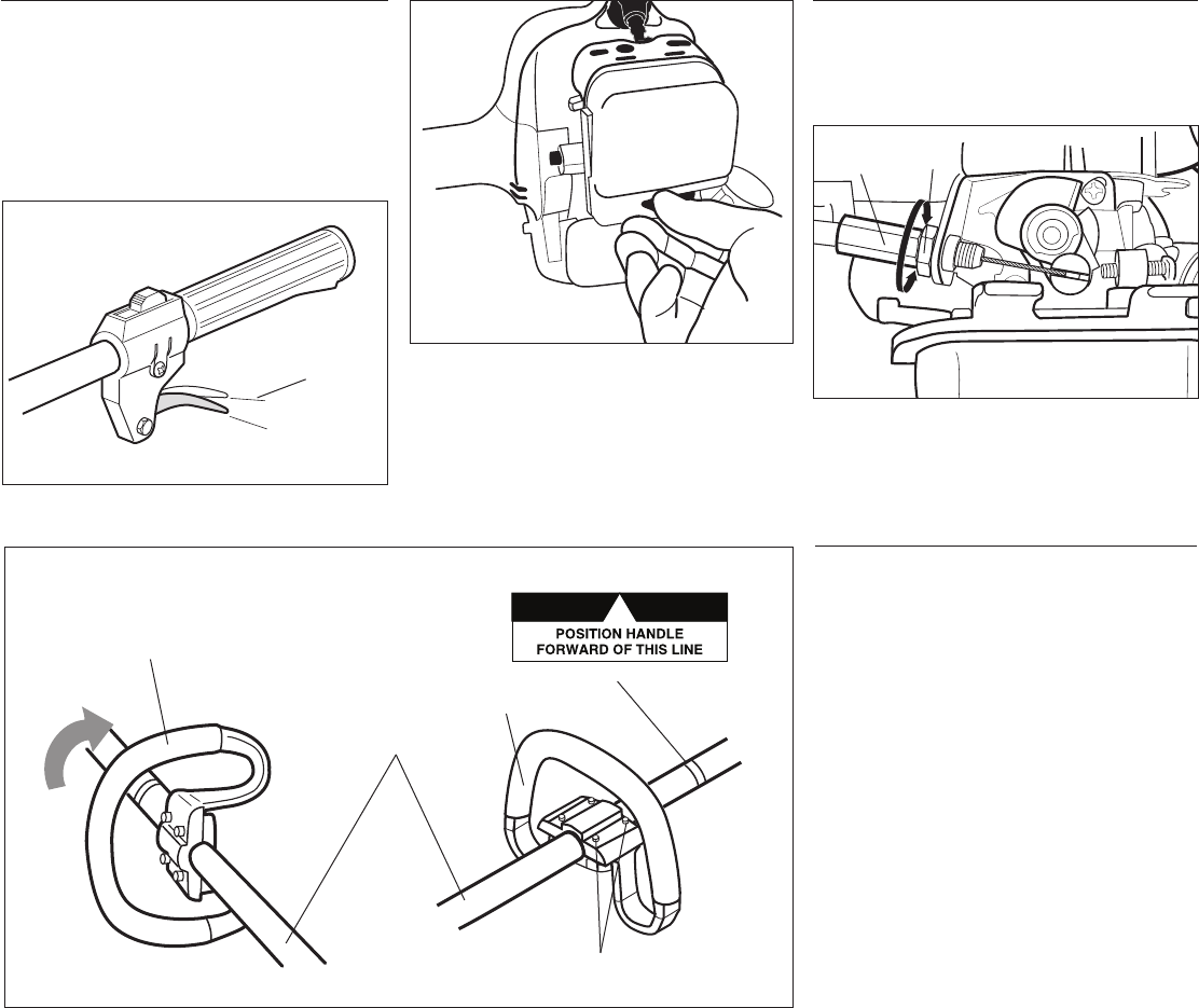
The handle is attached to the outer
tube at the factory and positioned
vertically. See Figure 8A.
Loosen the 4 socket-head cap screws
on the handle and rotate the handle 90
degrees. See Figure 8B.
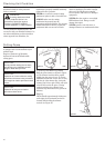
Position the handle forward of the
Handle Positioning Label at the best
position for operator comfort (usually
about 10 inches ahead of the throttle
housing).
Secure the handle by alternately tight-
ening the four socket-head cap screws
in a diagonal or “crisscross” fashion.
1.
2.
3.
4.
Handle
Assembly and Adjustments
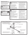
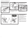
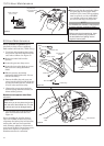
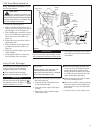
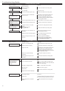
Adjust Throttle Lever Free Play
Loosen the air cleaner cover knob and re-
move the air cleaner cover. See Figure 6.
Loosen the lock nut on the cable ad-
juster. See Figure 6.
1.
2.
Figure 6
Figure 7
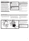
The throttle lever free play should be
approximately 3/16-1/4 inch (4-6 mm). See
Figure 5. Make sure that the throttle lever
operates smoothly without binding. If it
becomes necessary to adjust the lever free
play, follow the procedures and illustrations
that follow.
Figure 5
Turn the cable adjuster in or out as re-
quired to obtain proper free play 3/16-
1/4 inch (4-6 mm). See Figure 7.
Tighten the locknut.
3.
4.
Reinstall the air cleaner cover.5.
Figure 8B
Figure 8A
3/16-1/4 inch (4-6 mm)
Throttle Free Play
Lock
Nut
Cable
Adjuster
Handle
Outer Tube
Screws
Handle Positioning Label
Handle