


7
23105
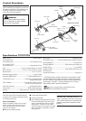
Assembly and Adjustments
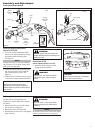
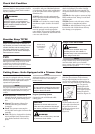
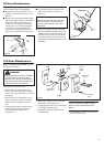
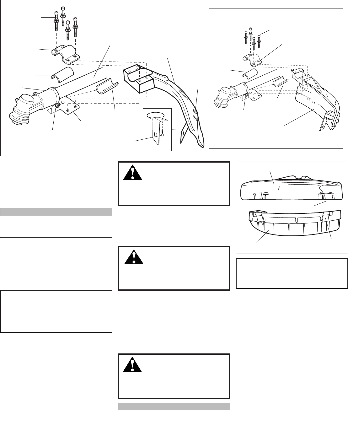
Cutting Attachment Shield
Figure 8
Cutting
Attachment
Shield
Outer
Tube
Socket-
Head Cap
Screw
Bracket
Shim
Clamp
Screw
Shim
Retaining
Nut
Cutting
Attachment
Shield
Mounting
Plate
Line Cutter
Figure 8A
Hex
Screws
Nuts
Install the Cutting Attachment
Shield T272/T272X.
1. Insert the cutting attachment shield
between the outer tube and the cutting
attachment shield mounting plate.
See Figure 8.
WARNING!
NEVER operate the unit without the
cutting attachment shield installed and
tightly secured!
CAUTION!
Make sure the clamp screw and
retaining nut are securely tightened
before tightening the four socket-head
cap screws.
NOTE:
It may be necessary to loosen the retaining
nut and clamp screw to adjust cutting attach
-
ment shield mounting plate.
2. Fit the two shims and the bracket over
the outer tube and loosely install the
four socket-head cap screws. See
Figure 8.
3. Tighten the four socket-head cap screws
to secure the cutting attachment shield.
WARNING!
The line cutter is very sharp. Wear
gloves to protect your hands when
handling.
To Change Position of Line Cutter.
1. Remove the 2 hex screws with a 4mm
hex wrench. See Figure 8A.
2. Rotate line cutter. See Figure 8A.
3. Reinstall the two hex screws and tighten
them securely.
NOTE:
Be careful to not lose the 2 nuts in the cutting
attachment shield, they are not captured.
The line cutter can be positioned in
2 positions to obtain different line length
for cutting.
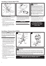
Bracket
T272
T272X
Sub-Shield T272X.
(when trimmer head is in use)
1. Attach the shield extension to the
cutting attachment shield.
WARNING!
NEVER use this machine without
sub-shield when using a trimmer
head.
CAUTION!
Make sure the sub-guard is completely
hooked at the hook receiver.
Sub-shield
Hook
Hook
Receiver
Cutting Attachment Shield
Bolt
Shim
Shim
Nut
Upper Clamp
Cutting Attachment Shield