


6
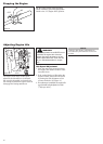
Assembly
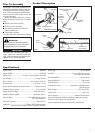
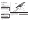
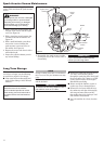
Index Screw
Gearcase/Cutter
Assembly
Mainshaft
Tube
Clamp
Outer Tube
1. Place the powerhead/outer Tube As-
sembly on a clean, flat surface, spark
plug facing up.
2. Use the 4mm hex wrench to loosen the
tube clamp and index screw. Verify that
the D-shaped shim washer is positioned
as shown in Figure 4.
CAUTION!
Do not remove the D-shaped shim
washer! The shim washer prevents
damage from overtightening the tube
clamp screw.
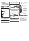
3. Slide the outer tube into the tube clamp
until the tube bottoms. If installation is
difficult, rotate the outer tube or main
shaft slightly until you feel the main-
shaft splines engage with the gearcase.
4. Position the outer tube so that the index
hole on the outer tube is aligned with
the index screw on the gearcase tube
clamp.
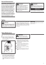
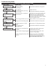
Connect the Powerhead/Outer
Tube to the Gearcase
Clamp Screw
Figure 4
D-Washer
Index
Hole
CAUTION!
Do not force the shaft tube into the
gearcase! Excessive force can dam-
age the shaft tube and mainshaft.
5. Using finger pressure only, thread the
index screw into the index hole located
on the outer tube until it bottoms out.
6. Tighten the index screw and the clamp
screw firmly.
NOTE:
It may be necessary to twist the outer tube
slightly for the index screw to be inserted fully.