


ASSEMBLY
FR240-FR162 01/11 Assembly Section 3-6
© 2011 Alamo Group Inc.
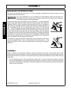
ASSEMBLY
Many of the equipment components are HEAVY (60 lbs or greater) and Special Lifting
Procedures are recommended. Use lifting assistance such as mechanical assistance, two
people, and proper lifting techniques when connecting or installing the driveshaft to reduce
the possibility of back injuries.
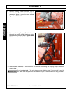
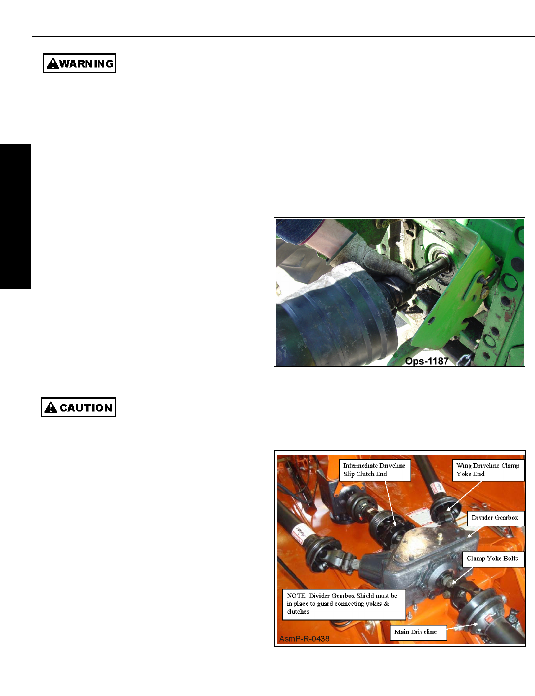
1. Remove bolts from main driveline implement
connection yoke and insert onto power divider
gearbox shaft. Install bolts according to
driveline clamp yoke instructions in this section.
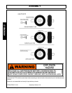
2. Inner center axle dual tire assemblies are
shipped bolted on wing mount tubes. Remove
transport bars from wings and lower each wing
so that inner tire and hub assembly can be
removed and installed on center axle. NOTE: It
will be necessary to raise each side of center
axle slightly so inner dual tires can be installed.
3. Install gearbox vents or vent dipsticks if not
installed.Check all gearbox lube levels.
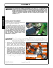
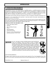
When attaching the Implement input driveline to the Tractor PTO, it is important that the
connecting yoke spring activated locking collar slides freely and the locking balls are seated
securely in the groove on the Tractor PTO shaft. Push and pull the driveline back and forth
several times to ensure it is securely attached. A driveline not attached correctly to the
Tractor PTO shaft could come loose and result in personal injury and damage to the
Implement.
(S3PT-17)
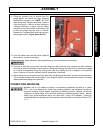
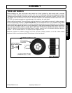
DRIVELINE ATTACHMENT
The driveline yoke and tractor PTO shaft must be
dirt free and greased for attachment.
To connect the mower driveline to the tractor PTO
output shaft, pull the driveline yoke collar back and
align the grooves and splines of the yoke with those
of the PTO shaft. Push the driveline yoke onto the
PTO shaft, release the locking collar, and position
the yoke until the locking collar balls are seated
onto the PTO shaft. Push and pull the driveline
back and forth several times to ensure a secure
attachment. OPS-R-0003_I