


ASSEMBLY
DM 07-02
© 2004 Alamo Group Inc.
Assembly Section 3-3
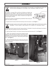
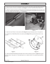
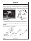
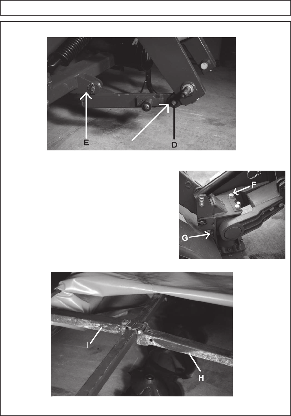
7. Install the cover frame on the cutter bar using two M16 x
35mm bolts (F), locking plate and lockwashers at the top and
three M16x35mm bolts and lockwashers (G) installed on the side.
(See Figure 5.) Torque the M16 bolts to 100 FT-LBS. Use a
thread-locking compound on top of 16mm bolts.(Note: Included
with kit is a packet of locktight.)
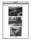
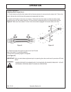
8. Attach the Front Cover Frame (H) and the Rear Cover Frame
(I) to the main cover frame using 3 M10 x 100mm bolts, six M10 x
25mm bolts. Do not tighten the hardware until both frames are
fully installed. (See Figure 6.) Only front frame folds, rear frame
is fixed in place.
Figure 5
Figure 6
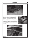
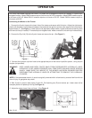
6. Connect the break away tongue to the frame using a break away pin and cotter keys(E). (See Figure 4.)
Figure 4