


ASSEMBLY
1480/1485/1495 01/11 Assembly Section 3-6
© 2011 Alamo Group Inc.
ASSEMBLY
Mounting Loader
Mounting is basically reverse of dismounting.
1. Slowly drive tractor into loader approximately 6” from loader mounts. Shut off tractor engine and set park-
ing brake.
2. Connect hydraulic hoses. (Match color code between male quick coupler and female quick coupler.) Make
sure couplers are clean before connecting together.
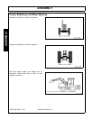
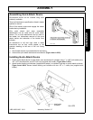
3. Start engine and release parking brake. Make sure lift cylinders are extended 6” to 8”. Stroke bucket cylin-
ders to raise or lower upright pin to clear each front mount pin saddle by approximately 1” (See Figure
Asm-L-0003).
4. Drive tractor forward until loader upright pins contact mount vertical stop surfaces just above the mount pin
saddles (See Figure Asm-L-0003). Extend bucket cylinders to FULLY seat both loader upright pins into
mount pin saddles and raise parking stands off ground. Retract lift cylinders, allowing tractor to move for-
ward. Continue until loader uprights have fully seated into back of mount tube saddles by retracting lift cyl-
inders to raise tractor front end (tires can be off ground).
5. Stop engine. Allow tractor front end to lower by relaxing ONLY lift cylinders with control lever.
6. Set parking brake. Insert two 1” hitch pins and lynch pins.
7. Raise loader, set parking brake, stop tractor engine.
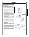
8. Remove lynch pins and clevis pins from parking stands, rotate stands into storage position and secure with
clevis pins and lynch pins (See Figure Asm-L-0001).
NOTE: If front wheel spacings were changed while loader was off tractor, tire clearances must be checked and
possibly adjusted to insure proper clearances.
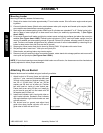
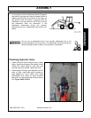
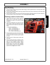
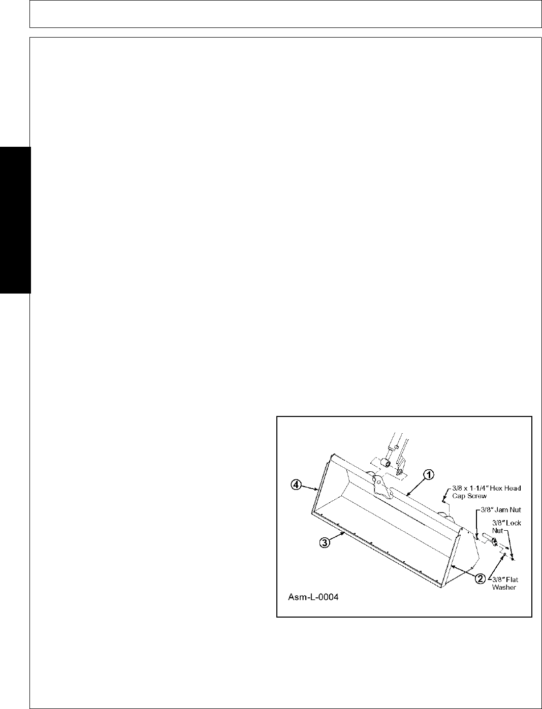
Attaching Pin on Bucket
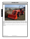
Material bucket can be installed using tool ordinarily available.
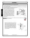
1. Attach bucket to lift boom frame and cylinders
with four 1” pins, use two 3/8 shoulder bolts and
3/8 lock nuts at upper pin (bucket cylinder). Use
two 3/8 x 1.25 hex bolts, 3/8 jam nut, 3/8 flat
washer and 3/8 lock nut at lower pin. Position
bolt with head on inside of outer bucket ear.
Fasten bolt to ear using 3/8 jam nut. Install pin
so pin head is over jam nut and retain with 3/8
flat washer and 3/8 lock nut.
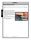
2. Install level indicator rod in level guide tube on
right bucket cylinder. Sandwich level indicator
rod angle between right inside bucket ear and
cylinder rod end.
3. Set bucket level on ground and adjust level
guide tube along bucket cylinder until end of
guide tube is flush with end of rod.