


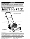
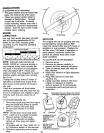

_CAUTION: Do not operate this mower
without the discharge guard or an entire
approved grass catcher in place. These
guards are for your protection and are
required by the American National
Standards Institute and Consumer
Products Safety Commission.
ACAUTION: Disconnect spark plug wire
from spark plug and place wire where it
cannot come in contact with plug.
Read these instructions and this manual
in its entirety before you attempt to
assemble or operate your new lawn
mower.
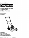
IMPORTANT: This lawn mower is
shipped WITHOUT OIL OR GASOLINE in
the engine.
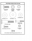
Your new lawn mower has been as-
sembled at the factory with the exception
of those parts left unassembled for
shipping purposes. All parts such as nuts,
washers, bolts, etc., necessary to com-
plete the assembly have been placed in
the parts bag. To ensure safe and proper
operation of your lawn mower, all parts
and hardware you assemble must be
tightened securely. Use the correct tools
as necessary to ensure proper tightness.
TOOLS REQUIRED FOR ASSEMBLY
A socket wrench set will make assembly
easier. Standard wrench sizes are listed.
(1) 5/16" Wrench (1) Adjustable Wrench
(1) 7/16" Wrench (1) 9/16" Wrench
(1) 1/2" Wrench (1) 3/4" Wrench
When right hand or left hand is men-
tioned in this manual, it means when you
are standing in the operating position,
behind the handle.
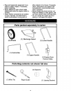
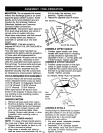
UNPACKCARTON
1. Remove all loose parts from carton.
2. Examine all items. Compare with list
of unassembled parts and hardware.
3. Remove lawn mower housing with
care. Avoid touching blade under
housing. Always wear gloves or other
protection when working under or
lifting mower.
ASSEMBLE LOWER HANDLE
NOTE: For ease of lower handle assem-
bly, raise rear of deck and block securely.
1. Position lower handle on deck so cut-
off flat is forward as shown.
2. Align holes in handle with holes in
deck as shown and assemble 3/8-16 x 6
3/4 hex bolts, flat washers, and
Iocknuts. Tighten securely.
3. Repeat for opposite side of mower.
Flat washers Locknuts
Hex
bolts
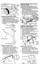
ASSEMBLE UPPER HANDLE
1. Position upper handle over lower
handle with small hole for mounting
up-stop bracket to right side and
assemble 1/4-20 x 1-1/2 hex bolts and
1/4-20 Iocknuts. Tighten securely.
ASSEMBLE UPSTOP BRACKET
2. Position upstop bracket on the right
inside of upper handle as shown.
3. Install the hex washer head screw into
the hole in up-stop bracket and upper
handle. Tighten securely.
AS VIEWED FROM FRONT OF MOWER
Up-stop
bracket-
Hex
washer
\
head \ /- -_',
screw - \ \
Lockouts
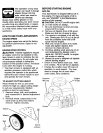
ASSEMBLE WHEELS
Cutting height is determined by assem-
bling the wheels in one of four possible
positions on the mower housing. All
wheels must be in the same height
position for even cutting.
1. For each wheel, assemble shoulder
bolt and spacer as shown
2. Assemble 1-1/4" diameter washer
(rear wheels only) and 3/8-16 Iocknut
on inside of mower housing and
tighten securely.