


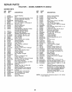
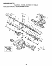
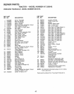
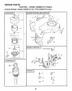

REPAIR PARTS
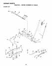
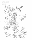
TRACTOR - - MODEL NUMBER 917.258542
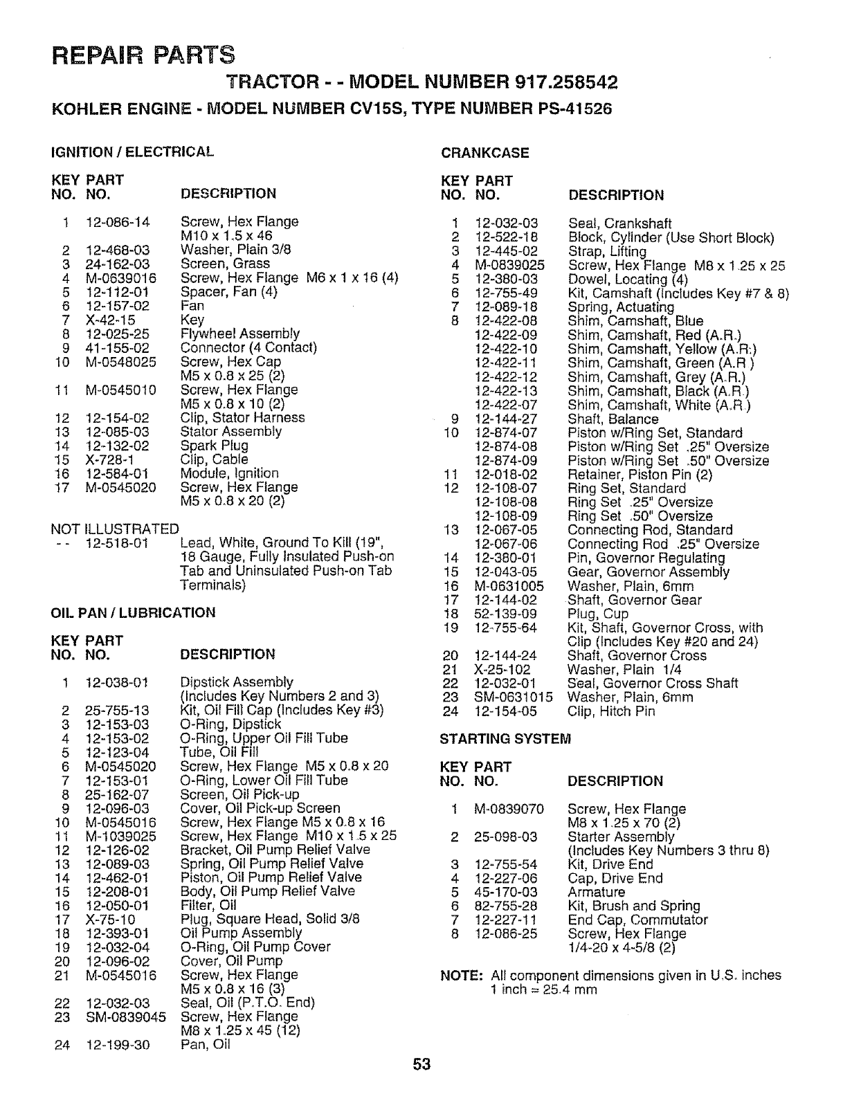
KOHLER ENGINE - MODEL NUMBER CV15S, TYPE NUMBER PS-41526
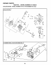
IGNITION / ELECTRICAL
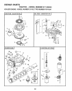
CRANKCASE
KEY PART KEY PART
NO. NO. DESCRIPTION NO. NO. DESCRIPTION
1 12-086-14 Screw, Hex Flange 1 12-032-03
M10x 1_5x46 2 12-522-18
2 12-468-03 Washer, Plain 3/8 3 127445-02
3 24-162-03 Screen, Grass 4 M-0839025
4 M-0639016 Screw, Hex Flange M6 x 1 x 16 (4) 5 t2-380-03
5 12-112-01 Spacer, Fan (4) 6 12-755-49
6 12-157-02 Fan 7 12-089-18
7 X-42-15 Key 8 12_422-08
8 12-025-25 Flywheel Assembly 12-422-09
9 41-155-02 Connector (4 Contact) 12-422-10
10 M-0548025 Screw, Hex Cap 12-422-11
M5 x 0_8 x 25 (2) 12-422-12
11 M-0545010 Screw, Hex Flange 12-422_13
M5 x 0.8 x 10 (2) 12-422-07
12 12_154-02 Clip, Stator Harness 9 12-I44-27
13 12-085-03 Stator Assembly 10 12-874-07
14 12-132-02 Spark Plug 12-874-08
15 X-728-1 Clip, Cable 12-874-09
16 12-584-01 Module, Ignition 11 12-018-02
17 M-0545020 Screw, Hex Flange 12 12-108_07
M5 x 0.8 x 20 (2) 12-108-08
12-t 08-09
NOT ILLUSTRATED 13 12-067-05
- - 12-518-01 Lead, White, Ground To Kill (I9", 12-067-06
18 Gauge, Fully Insulated Push-on 14 12-380-01
Tab and Uninsulated Push-on Tab 15 12-043-05
Terminals) 16 M-0631005
17 12-144-02
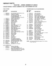
OIL PAN 1 LUBRICATION 18 52-139-09
19 12_755_64
DESCRIPTION
KEY PART
NO. NO.
t2-038-01
2 25-755-t3
3 12-153-03
4 12-t53-02
5 12-t23-04
6 M-0545020
7 12-t53-01
8 25-162-07
9 12-096-03
10 M-0545016
11 M-1039025
12 12-126-02
13 12-089-03
14 12-462-0I
15 12-208-01
16 t2-050-01
17 X-75-10
18 12-393-01
19 12-032-04
20 12-096-02
21 M-0545016
22 12-032-03
23 SM-0839045
Dipstick Assembly
(Includes Key Numbers 2 and 3)
Kit, Oii Fill Cap (Includes Key #3)
O-Ring, Dipstick
O-Ring, Upper Oil Fill Tube
Tube, Oil Fill
Screw, Hex Flange M5 x 0.8 x 20
O-Ring, Lower Oil Fill Tube
Screen, Oil Pick-up
Cover, Oil Pick-up Screen
Screw, Hex Flange M5 x 0.8 x 16
Screw, Hex Flange M10 x 1.5 x 25
Bracket, Oil Pump Relief Valve
Spring, Oil Pump Relief Valve
Piston, Oil Pump Relief Valve
Body, Oit Pump Relief Valve
Fi}ter, Oil
Plug, Square Head, Solid 3/8
Oil Pump Assembly
O-Ring, Oil Pump Cover
Cover, Oil Pump
Screw, Hex Flange
M5 x 0.8 x 16 (3)
Seal, Oil (PoT.Co End)
Screw, Hex Flange
M8 x 1_25x 45 (12)
Pan, Oil
53
24 12-199-30
20 124144-24
21 X-25-102
22 12-032-01
23 SM-0631015
24 12-154-05
Seal, Crankshaft
Block, Cylinder (Use Short Block)
Strap, Lifting
Screw, Hex Flange M8 x 1.25 x 25
Dowel, Locating (4)
Kit, Camshaft (includes Key #7 & 8)
Spring, Actuating
Shim, Camshaft, Blue
Shim, Camshaft, Red (A.R)
Shim, Camshaft, Yellow (A.R:)
Shim, Camshaft, Green (A.R)
Shim, Camshaft, Grey (AR.)
Shim, Camshaft, Black (AR)
Shim, Camshaft, White (A.R.)
Shaft, Balance
Piston w/Ring Set, Standard
Piston w/Ring Set _25" Oversize
Piston w/Ring Set .50" Oversize
Retainer, Piston Pin (2)
Ring Set, Standard
Ring Set .25" Oversize
Ring Set ..50" Oversize
Connecting Rod, Standard
Connecting Rod .25" Oversize
Pin, Governor Regulating
Gear, Governor Assembly
Washer, Plain, 6mm
Shaft, Governor Gear
Plug, Cup
Kit, Shaft, Governor Cross, with
Clip (Includes Key #20 and 24)
Shaft, Governor Cross
Washer, Plain 1/4
Seal, Governor Cross Shaft
Washer, Plain, 6mm
Clip, Hitch Pin
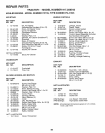
STARTING SYSTEM
KEY PART
NO. NOr DESCRIPTION
3
4
5
6
7
8
M-0839070
25-098-03
12-755-54
12-227-06
45-170-03
82-755-28
12-227-11
12-086-25
Screw, Hex Flange
M8 x 1_25 x 70 (2)
Starter Assembty
(includes Key Numbers 3 thru 8)
Kit, Drive End
Cap, Drive End
Armature
Kit, Brush and Spring
End Cap, Commutator
Screw, Hex Flange
!/4-20 x 4-5/8 (2)
NOTE: AII component dimensions given in U.S. inches
1 inch = 254 mm