


CE
AND ADJUSTMENTS
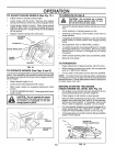
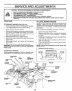
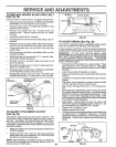
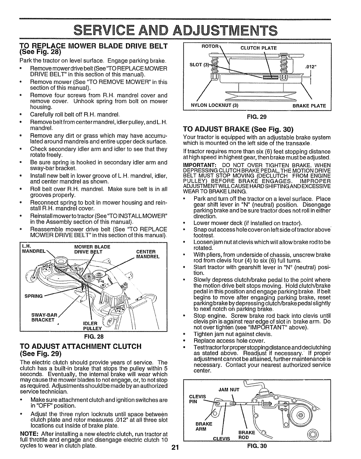
TO REPLACE MOWER BLADE DRIVE BELT
(See Fig. 28)
Park the tractor on level surface_ Engage parking brake.
o Remove mower drive belt (See'q'O REPLACE MOWER
DRIVE BELT" in this section of this manual).
. Remove mower (See "TO REMOVE MOWER" in this
section of this manual).
. Remove four screws from Roll. mandrel cover and
remove cover° Unhook spring from bolt on mower
housing°
° Carefully roll belt off R.H. mandrel,.
° Remove belt from center mandrel, idler pulley, and L.Ho
mandrel
° Remove any dirt or grass which may have accumu-
lated around mandrels and entire upper deck surface°
° Check secondary idler arm and idler to see that they
rotate freely,,
- Be sure spring is hooked in secondary idler arm and
sway-bar bracket°
° Install new belt in lower groove of L.H. mandrel, idler,
and center mandrel as shown.
° Roll belt over RoHomandrel. Make sure belt is in all
grooves properly°
• Reconnect spring to bolt in mower housing and rein-
stall RoHomandrel coven
° Reinstall mower to tractor (See"TO INSTALL MOWER"
in the Assembly section of this manual).
o Reassemble mower drive belt (See "TO REPLACE
MOWER DRIVE BELT" in this section of this manual),,
L,H, MOWER BLADE
DRIVE _LT CENTER
MANDREL
SPRING
SWAY-BAR,/
BRACKET
PULLEY
FIG. 28
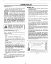
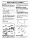
TO ADJUST ATTACHMENT CLUTCH
(See Fig. 29)
The electric clutch should provide years of service_ The
clutch has a built_in brake that stops the pulley within 5
seconds,, Eventually, the internal brake will wear which
may cause the mower blades to not engage, or, to not stop
as required. Adjustments should be made by an authorized
service technician,,
o Make sure attachment clutch and ignitionswitches are
in "OFF" position.
° Adjust the three nylon Iocknuts until space between
clutch plate and rotor measures ,,012"at all three slot
locations cut inside of brake plate.,
NOTE: After installing a new electric clutch, run tractor at
full throttle and engage and disengage electric clutch 10
cycles to wear in clutch plate.
21
NYLON LOCKNUT (3)
FIG, 29
BRAKE PLATE
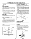
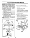
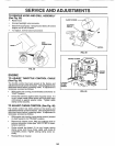
TO ADJUST BRAKE (See Fig. 30)
Your tractor is equipped with an adjustable brake system
which is mounted on the left side of the transaxle,
Iftractor requires more than six (6) feet stopping distance
at high speed in highest gear, then brake must be adjusted,
IMPORTANT: DO NOT OVER TIGHTEN BRAKE. WHEN
DEPRESSING CLUTCH BRAKE PEDAL, THE MOTION DRIVE
BELT MUST STOP MOVING (DECLUTCH FROM ENGINE
PULLEY) BEFORE BRAKE ENGAGES. iMPROPER
ADJUSTMENTWILLCAUSE HARDSHIFTINGAND EXCESSIVE
WEAR TO BRAKE LINING,,
o Park and turn off the tractor on a level surface. Place
gear shift lever in "N" (neutral) position° Disengage
parking brake and be sure tractor does not roll in either
direction°
° Lower mower deck (if installed on tractor),,
° Snap out access hole cover on left side of tractor above"
footrest..
• Loosen jam nut at clevis which will allow brake rod to be
rotated.
• With pliers, from underside of chassis, unscrew brake
rod from clevis four (4) to six (6) full turns.
o Start tractor with gearshift lever in "N'; (neutral) posi-
tion.
° Slowly depress clutch/brake pedal to the point where
the motion drive belt stops moving,, Hold clutch/brake
pedal inthis position and engage parking brake., If belt
begins to move after engaging parking brake, reset
parking brake by depressing clutch/brake pedal slightly
to next notch on parking brake.
. Stop engine. Screw brake rod back into clevis until
clevis pin is against rear edge of slot in brake arm_ Do
not over tighten (see "IMPORTANT" aboVe),,
° Tighten jam nut against clevis,,
° Replace access hole cover.
° Test tractor for properstopping distance and declutching
as stated above. Readjust if necessary. If proper
adjustment cannot be attained, further maintenance is
necessary. Contact your nearest authorized service
center°
' JAM NUT __
BRAKE ! \ \k\ IOI
CLEVIS ROD "_
FIG.30