


ASSEMBLY
Read these iv,sttuctions and Operator's Manual in its en-
tirety before you attempt to assemble or operate your new
high pressure washer° Your high pressure washer has, for
the most part, been asserr_ed at the factory, except those
parts leftunassembted. Before you can operate your new
highpressure washer, you mustassemble the wheel kitand
property connect the high pressure hose.
IF YOU HAVE ANY PROBLEMS WITH THE ASSEMBLY
OF YOUR PRESSURE WASHER, PLEASE CALL THE
PRESSURE WASHER HELPLINE AT 1-800-_-3136.
TOOLS REQUIRED FOR ASSEMBLY
o Mallet
= 2 adjustable wrenches OR the following wrenches:
=, 5/16" (8mm) combination wrench
= 1/2" (13mm) combination wrench
- 5/8' (16mm) combination wrench
= 11/16" (18mm) combination wrench
= 7/8" (22ram) combination wrench
= 15/16" (24mm) combination wrench
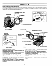
TO REMOVE PRESSURE WASHER FROM
CARTON
=, Remove two boxes marked "PARTS INSIDE" and re-
move the parts contained in both boxes.
= Remove unit with one hand under pump and one hand
under recoil starter.
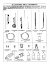
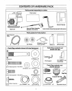
Refer to Page 6, "Contents of Hardware Pack" for an
illustrated listingof allthe items included with yourpressure
washer, Become familiar with each piece before assem-
bling the pressure washer,, Check all contents against the
illustrations on Page & If any parts are missing or dam-
aged, call the Pressure Washer Helpline at 1-800-222-
3136,
HOW TO SET UP YOUR PRESSURE WASHER
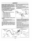
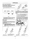
TO INSTALL THE WHEEL KIT
Installing the wheel kit requires the tools listed, the guide
handle and items included in the parts carton°
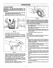
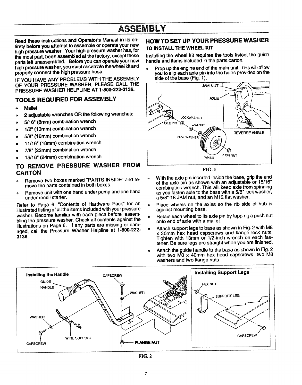
° Prop up the engine end of the main unit. This willallow
you to slipeach axle pin into the holes provided on the
side ofthe base (Fig 1).
JAM
LOGK1NASHER
JAM NUT
FLATv
_L
REVERSE ANGLE
FIG. 1
With the axle pin inserted inside the base, grip the end
of the axle pin as shown with an adjustable or 15/16"
combination wrench. This will keep axle from spinning
as you fasten axle to the base with a 5/8 lock washer,
a 5/8"-18 JAM nut, and an M12 flat washer..
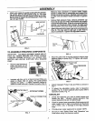
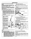
o Place wheels on the axles so the rib side of hub is
against mounting base.
= Retain each wheel to itsaxle pin by tapping a push nut
onto end of axle with a mallet.
° Attach support legs to base as shown in Fig, 2 with M8
x 20mm hex head capscrews and flange lock nuts,.
Tighten with 13mm or 1/2-inch wrench on each fas-
tener.. Be sure legs are straight when you are tinished_
• Attach the guide handle to the base as shown in Fig, 2
with two M8 x 40mm hex head capscrews, two M8
washers and two flange nuts.
Installingthe Handle
GUIDE
HANDLE
WASHER
\
CAPSCREW
WIRE SUPPORT
CAPSCREW
_NUT
Installing Support Legs
CAPSC
FIG. 2