


................ ii i i
SERVICE AN
i1, i,,, , ii m,,,,,,,,,,H ii ,,,,,n
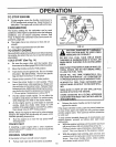
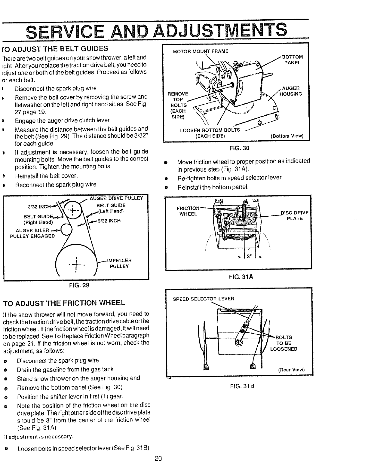
rO ADJUST THE BELT GUIDES
here are two belt guides on your snow thrower, a left and
ight After you replace the traction drive belt, you need to
_djust one or both of the belt guides Proceed as follows
or each belt:
Disconnect the spark plug wire
D Remove the belt cover by removing the screw and
flatwasher on the left and right hand sides See Fig
27 page 19.
D Engage the auger drive clutch lever
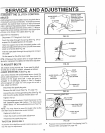
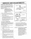
Measure the distance between the belt guides and
the belt (See Fig 29) The distance should be 3/32"
for each guide.
IH H, r I, IHHI I, I I I1,,,1,1
ADJUSTIVIE TS
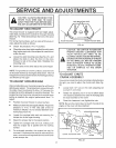
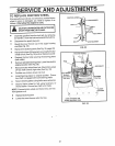
MOTOR MOUNT FRAME
\\ _._ BOTTOM
SIDE) I
LOOSEN BOTTOM BOLTS
IEAC.S,DEI................ cao.t.lo,.Vi.ewl
D If adjustment is necessary, loosen the belt guide
mounting bolts. Move the belt guides to the co_'rect
position. Tighten the mounting bolts
D Reinstall the belt cover.
Reconnect the spark plug wire
......................, ._..-_ _ ._'UGER DRIVE PULLEY
3132 INCH"__ BELT GUIDE
BELT GUIDF_" "_._ _,.(Le|l Hand)
(Right Hand)A-- _\_"3132 INCH
_IMPELLER
FIG, 29
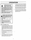
TO ADJUST THE FRICTION WHEEL
If the snow thrower will not move forward, you need to
check thetraction drive bell, the traction drive cable or the
Mction wheel Ifthe frictionwheel is damaged, itwilt need
to be repiaced. See To Replace Friction Wheel parag raph
on page 21 If the friction wheel is not worn, check the
adjustment, as follows:
• Disconnect the spark plug wire
o Drain the gasoline from the gas tank
g Stand snow thrower on the auger housing end
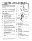
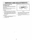
® Remove the bottom panel (See Fig 30)
® Position the shifter lever in first (1) gear
o Note the position of the friction wheel on the disc
drive plate. The right outer side of the disc drive plate
should be 3" from the center of the friction wheel
(See Fig 3tA)
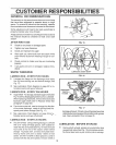
If adjustment is necessary:
FIG. 30
• Move frictionwheel to proper position as indicated
in previous step (Fig 31A).
• Re-tighten bolts in speed selector Iever
® Reinstall the boitom panel.
IIH H IHI H,H ,i HH,,
_____DIscDR=VE
__ _ PLATE
3"1<
i,i ii
FIGo31A
SPEED SELECTOR LEVER
(Rear View)
FIG. 31B
= Loosen bolts in speed selector lever (See Fig 31B)
2O