


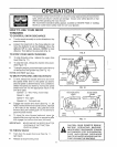
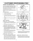
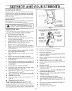
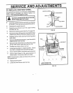
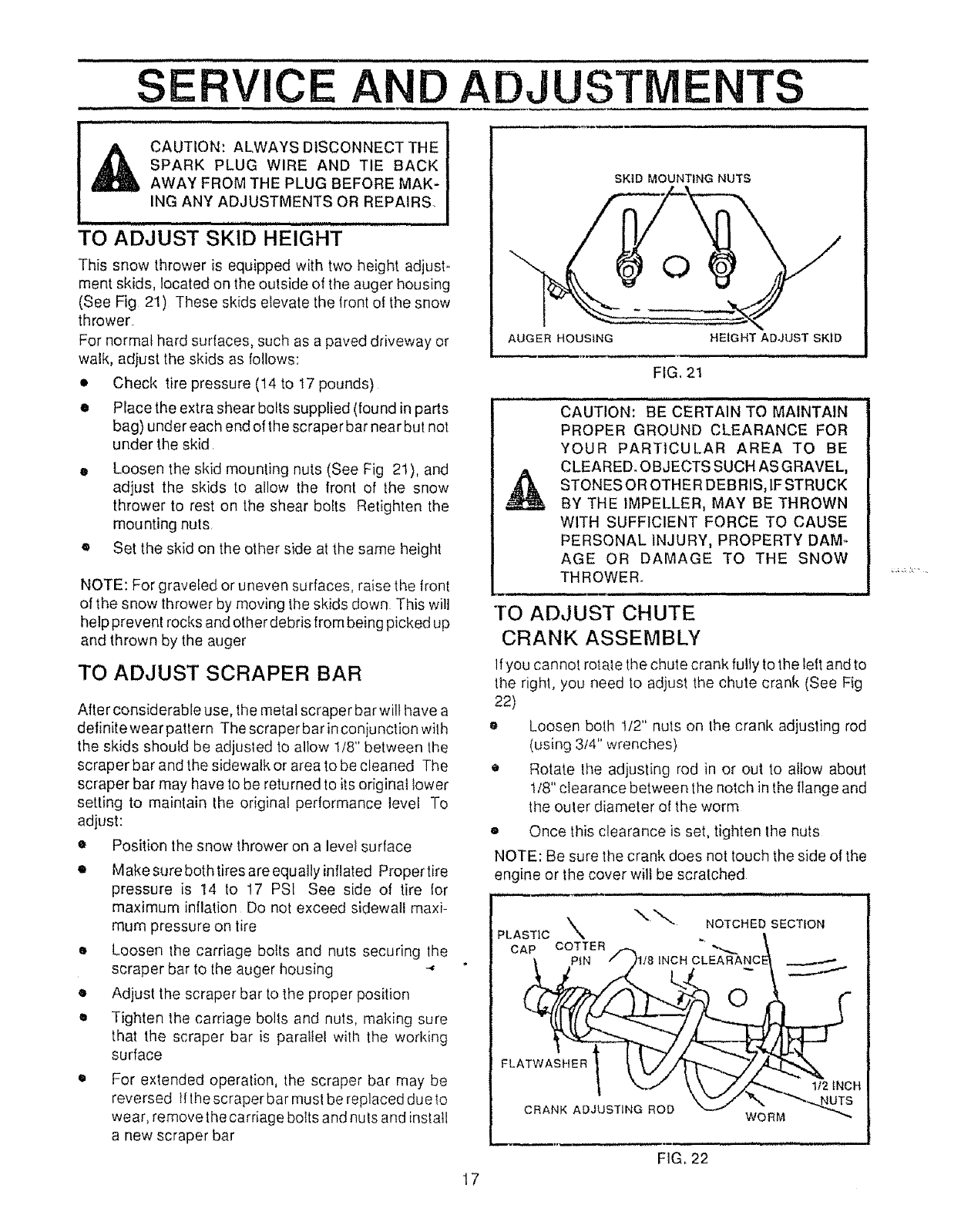
Thissnowthroweris equippedwithtwoheightadjust-
meritskids,locatedonthe outside of the auger housing
(See Fig 21) These skids elevate the front of the snow
thrower
For normal hard surfaces, such as a paved driveway or
walk, adjust the skids as follows:
• Check tire pressure (14 to 17 pounds)
• Place the extra shear bolts supplied (found in parts
bag) under each end of the scraper bar near but not
under the skid
• Loosen the skid mounting nuts (See Fig 21), and
adjust the skids to allow the front of the snow
thrower to rest on the shear bolts Retighten the
mounting nuts,
• Set the skid on the other side at the same height
NOTE: For graveled or uneven surfaces, raise the front
of the snow thrower by moving the skids down This wilt
help prevent rocks and other debris from being picked up
and thrown by the auger
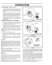
TO ADJUST SCRAPER BAR
After considerable use, the metal scraper bar wilt have a
definitewearpattern The scraperbarinconjuncfionwith
the skids should be adjusted to allow tt8" between the
scraper bar and the sidewalk or area tobe cleaned The
scraper bar may have to be returned to its original lower
setting to maintain the original pertormance level To
adjust:
• Position the snow thrower on a level surface
• Make sure both tires are equally inflated Propertire
pressure is 14 to 17 PSI See side of tire {or
maximum inflation Do not exceed sidewall maxi-
mum pressure on tire
• Loosen the carriage bolts and nuts securing lhe
scraper bar to the auger housing -"
o Adjust the scraper bar to the proper position
• Tighten the carriage bolts and nuts, making sure
that the scraper bar is parallel with the working
surface
SKID MOUNTING NUTS
For extended operation, the scraper bar may be
reversed lflhe scraper bar must be replaced due to
wear, remove the carriage bolts and nuls and install
a new scraper bar
AUGER HOUSING
HEIGHT ADJUST SKID
FIG. 2t
........................... _ i i i iinnllU
CAUTION: BE CERTAIN TO MAINTAIN
PROPER GROUND CLEARANCE FOR
YOUR PARTICULAR AREA TO BE
CLEARED, OBJECTS SUCH AS GRAVEL,
STONES OR OTHER DEBRIS, IF STRUCK
BY THE IMPELLER, MAY BE THROWN
WITH SUFFICIENT FORCE TO CAUSE
PERSONAL INJURY, PROPERTY DAM-
AGE OR DAMAGE TO THE SNOW
THROWER..
i , ,i ,,, i i
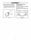
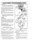
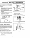
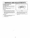
TO ADJUST CHUTE
CRANK ASSEMBLY
If you cannot rotate the chute crank fully to the left and to
the right, you need to adjust the chute crank (See Fig
22)
o Loosen both t/2" nuts on the crank adjusting rod
(using 3/4" wrenches)
• Rotate the adjusting rod in or out to allow about
t/8" clearance between the notch in the flange and
the outer diameter o! the worm
e Once this clearance is set, tighten the nuts
NOTE: Be sure the crank does not touch the side of the
engine or the cover will be scratched
PLASTIC\. NOTC.EO.SECT ON
CAP COTTER _ "_,_._
_. PiN /h/8 INCH CLEARANCE] .__,..-..-..
FL
_ '-.,.-tz \ \ /z Z"_ 112 iNCH
C.AN ,,O.',ST,NORO0
" WORM
FIG,, 22
17