


SERVMCE
,,,H,
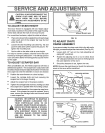
CAUTION: ALWAYS DISCONNECTTHE
SPARK PLUG WIRE AND TIE BACK
AWAY FROM THE PLUG BEFORE
MAKING ANY ADJUSTMENTS OR RE-
PAIRS. .............................
m=,
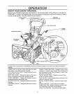
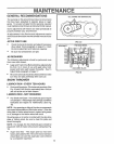
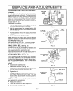
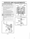
TO ADJUST SKnDS HEIGHT
ANDADJUST E TS
SKID MOUNTING NUTS
HEIGHT ADJUST SKID
This snow thrower is equipped with two height adjust-
ment skids, located on the outside of the auger housing.
These skids elevate the front of the snow thrower°
For normal hard surfaces, adjust the skids as follows:
o Place extra shear' bolts supplied (found inparts bag)
under each end of the scraper bar near but not
under the skid.
e Loosen the skid mounting nuts (See Fig 19) and
push the skid down until it touches the ground. Re-
tighten the mounting nuts.
= Set the skid on the other side at same height..
For rocky or uneven surfaces, raise the front of the snow
thrower by moving the skids down. This will help prevent
rocks and other debris from being picked up and thrown
by the auger.
TO ADJUST SCRAPER BAR
After considerable use, the metal scraper bar will have a
definite wear pattern. The scraper barin conjunctionwith
the skids should always be adjusted to allow 1/8" between
the scraper bar and the sidewalk or area to be cleaned_
e Position the snow thrower' on a level surface
e Loosen t!le carriage bolts and nuts securing the
scraper bar to the auger housing
e Adjust the scraper' bar to the proper position..
e Tightenthe carriage bolts and nuts, making sure that
the scraper bar is parallel with the working surface..
® After extended operation, the scraper bar may be re-
versed.. If the scraper bar must be replaced due to
wear, remove the carriage bolts and nuts and install
a new scraper bar.
"' cA ' ,o .........................
N: BE CERTAIN TO MAINTAIN
PROPER GROUND CLEARANCE FOR
YOUR PARTICULAR AREA TO BE
CLEARED. OBJECTS SUCH AS GRAVEL,
A ROCKS OR OTHER DEBRIS, IF STRUCK
BY THE IMPELLER, MAY BE THROWN
WITH SUFFICIENT FORCE TO CAUSE
PERSONAL INJURY, PROPERTY DAM-
AGE OR DAMAGE TO THE SNOW
THROWER.
................ .............. : ,,,,luu
HEIGHT ADJUST SKID
FIG. 19
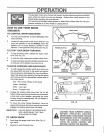
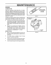
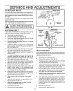
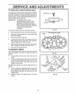
TO ADJUST CHUTE
CRANK ASSEMBLY
if you cannot rotate the chute crank fully to the left and to
the right, you needto adjust the chute crank (See Fig. 20)_
e Loosen both 1/2" nuts on the crank adjusting rod
(using 3/4" wrenches).
® Rotate the adjusting rod in or out to allow about
1/8" clearance between the notch in the flange and
the outer' diameter of the worm°
e Once this clearance is set, tighten the nuts.
NOTE: Be sure the crank does not touch the carburetor
cover or the cover will be scratched
PLASTIC _. NOTCHED SECTION
CAP COTTER
PIN NCH CLEARANC
ROD
FIG. 20
1/2 INCH
WORM
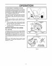
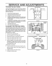
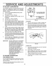
TRACTION
CLUTCH CONTROL LEVER
LEVER MUST BE IN FULL
FORWARD POSI-
TION (Just Contact-
"Z" FITI"ING ing Plastic Bumper)
WHEN CHECKING
16
. "PLASTIC BUMPER
FIG. 21