


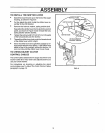

S CEAN ADJUSTME TS
i
CAUTION: ALWAYS DISCONNECT THE
SPARK PLUG WIRE AND TIE BACK AWAY
FROM THE PLUG BEFORE MAKING ANY
ADJUSTMENTS OR REPAIRS.
i i
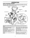
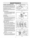
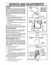
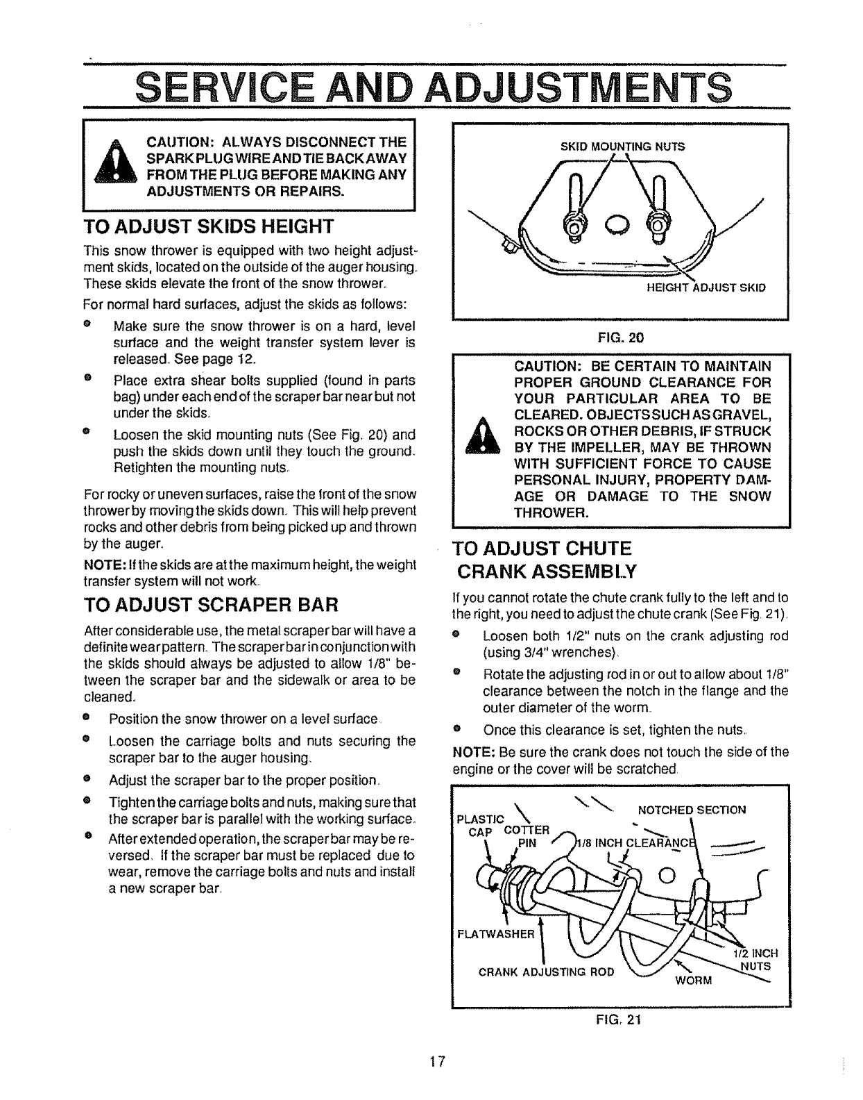
TO ADJUST SKIDS HEIGHT
This snow thrower is equipped with two height adjust-
ment skids, located on the outside of the auger housing
These skids elevate the front of the snow thrower°
For normal hard surfaces, adjust the skids as follows:
e Make sure the snow thrower is on a hard, level
surface and the weight transfer system lever is
released See page 12.
o Place extra shear bolts supplied (found in parts
bag) under each end of the scraper bar near but not
under the skids
@
Loosen the skid mounting nuts (See Fig 20) and
push the skids down until they touch the ground.
Retighten the mounting nuts
For rocky or uneven surfaces, raise the front of the snow
thrower by moving the skids down This will help prevent
rocks and other debris from being picked up and thrown
by the auger°
NOTE: tfthe skids are at the maximum height, the weight
transfer system will not work
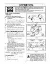
TO ADJUST SCRAPER BAR
After considerable use, the metal scraper bar wilt have a
definite wear pattern. The scraperbar inconjunction with
the skids should always be adjusted to allow 1/8" be-
tween the scraper bar and the sidewalk or area to be
cleaned.
®
o
o
o
o
Position the snow thrower on a level surface
Loosen the carriage bolts and nuts securing the
scraper bar to the auger housing_
Adjust the scraper bar to the proper position
Tighten the carriage bolts and nuts, making su rethat
the scraper bar is parallel with the working surface.
After extended operation, the scraper bar may be re-
versed, if the scraper bar must be replaced due to
wear, remove the carriage bolts and nuts and install
a new scraper bar
SKID MOUNTING NUTS
HEIGHT ADJUST SKID
/ /1//i ill ill illl /i Jl i ii ii i M_
FIG. 20
CAUTION: BE CERTAIN TO MAINTAIN
PROPER GROUND CLEARANCE FOR
YOUR PARTICULAR AREA TO BE
CLEARED. OBJECTS SUCH AS GRAVEL,
ROCKS OR OTHER DEBRIS, IF STRUCK
BY THE IMPELLER, MAY BE THROWN
WITH SUFFICIENT FORCE TO CAUSE
PERSONAL INJURY, PROPERTY DAM-
AGE OR DAMAGE TO THE SNOW
THROWER.
i ill i i llllll/// // i i i
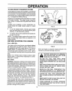
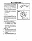
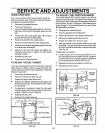
TO ADJUST CHUTE
CRANK ASSEMBLY
If you cannot rotate the chute crank fully to the left and to
the right, you need to adjust the chute crank (See Fig 21)
e Loosen both 1/2" nuts on the crank adjusting rod
(using 3/4" wrenches)
o Rotate the adjusting rod in or out to allow about t/8"
clearance between the notch in the flange and the
outer diameter of the worm
• Once this clearance is set, tighten the nuts
NOTE: Be sure the crank does not touch the side of the
engine or the cover will be scratched
I
FLATWASHER 1
CRANK ADJUSTING ROD
FIG_ 21
WORM
1/2 INCH
17