


REV 10855
2-12-08
12
4. Operator's Manual
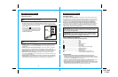
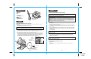
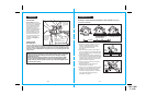
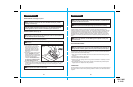
PARTS LIST
(Fig. 1)
1. Saw
2. Blade
(unassembled)
3. Blade Wrench
(for changing the blade)
UNPACKING cont.
!
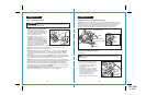
2. Place saw on its side on a flat surface.
3. To loosen the depth-of-cut adjustment lever, raise the saw up all the way and tighten
lever. This gives you easier access to blade mounting area (see Fig. 2a).
4. Place saw upright, on its base and on a flat surface (see Fig. 2a).
5. To loosen the spindle clamping screw “A”, depress the spindle lock button (see Fig. 2).
Place the blade wrench on the spindle clamping screw “A”. Move the wrench back and
forth until you feel the spindle lock button depress further and it locks the blade in
position so the spindle clamping screw can be removed. Keeping the spindle lock button
firmly depressed, turn the spindle screw counterclockwise to remove.
WARNING:
To prevent personal injury, ALWAYS disconnect the plug from
power source BEFORE assembling parts, making adjustments or installing blades.
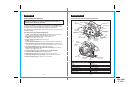
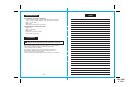
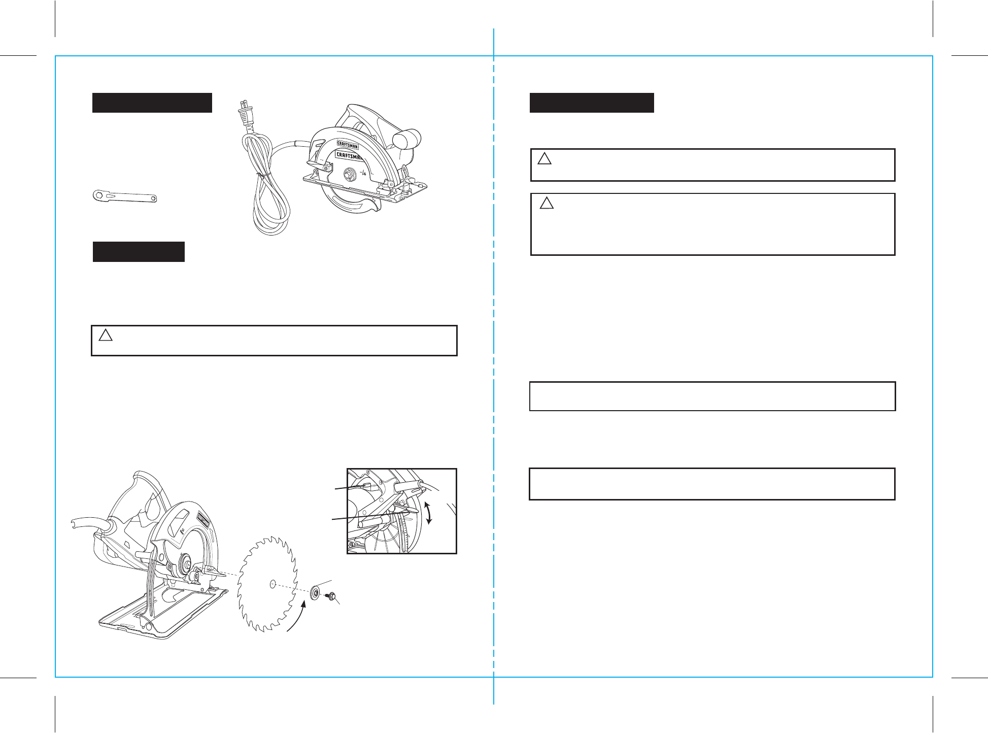
INSTALLING THE BLADE (Figs. 2 and 2a)
1. Saw
should not
be plugged into power source.
ASSEMBLY
Carefully remove the blade from its packing, inspect it to be sure that it is not cracked or
damaged.
Depth-of-Cut
Adjustment Lever
Fig. 2a
“A” Spindle
Clamping Screw
Outer “D” Washer
®
Blade Rotation
teeth point up at front
Fig. 2
Spindle
Lock Button
7
1
®
Amp
s
12
Loosen
Tighten
13
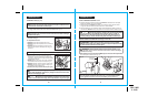
11. Replace the “D” washer.
12. Firmly hold down spindle lock button as you replace the spindle screw and hand
tighten it in a clockwise direction. Then use blade wrench to tighten the spindle
clamping screw thoroughly.
6. Completely remove the spindle clamping screw “A” and the outer “D” washer
(see Fig. 2a).
7. The remaining washer is the inner bushing washer that fits around the spindle shaft
and it does not need to be removed.
8. Put a drop of oil onto the inner bushing washer and outer “D” washer where they will
touch the blade.
9. Raise lower blade guard using the blade guard lever and hold it in the raised position
for the next step.
10. Place the saw blade inside the lower blade guard, onto the spindle shaft and against
the inner bushing.
NOTE: The teeth of the blade should point upward at the front of the saw as
shown in (Fig. 2a).
NOTE: NEVER use a blade that is too thick to allow the “D” washer to engage
with the flat side of the spindle.
WARNING: BE SURE to wear protective work gloves while handling a saw
blade. The blade can injure unprotected hands.
!
ASSEMBLY cont.
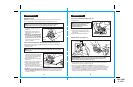
WARNING: A 7
1
/4-inch blade is the maximum blade capacity of your saw.
A larger than 7
1
/4-inch blade will come in contact with the blade guards. Also,
NEVER use a blade that is so thick that it prevents the outer blade washer from
engaging with the flat side of the spindle. Blades that are too large or too thick
can result in an accident causing serious injury.
!
INSTALLING THE BLADE cont. (Figs. 2 and 2a)
REMOVING THE BLADE (Figs. 2 and 2a)
1. Unplug the saw.
2. Follow steps 2. through 6. of “INSTALLING THE BLADE” and remove the blade
(see Fig. 2a).