


9
Section 4
5. Ammeter (Figure 4-1). Indicates the condition of
the charging system. When the engine is running the
needle should be toward the positive end of the meter.
If the needle is toward the negative end of the meter,
this indicates a discharge condition and the machine
should be taken in for service.
6. Hourmeter (Figure 4-1). Indicates the number of
hours the engine has been operated. It operates
whenever the ignition key switch is in the ON
position. It can be used to keep track of maintenance
intervals and the amount of time required to perform
various tasks.
7. Fuse Holders (Figure 4-1). Two 20-amp fuses
protect the mowers electrical system. To replace
fuses, pull fuse out of the socket and install a new
fuse.
8. Left Steering Control (Figure 4-1). Used to control
the mower's left wheel when traveling forward or
reverse.
9. Right Steering Control (Figure 4-1). Used to
control the mower's right wheel when traveling
forward or reverse.
10. Parking Brake Control (Figure 4-1). Used to
engage and disengage the parking brakes. Pull the
lever back to engage the parking brakes. Push the
lever forward to disengage the parking brakes.
11. Fuel Tank Gauge (Figure 4-1). Indicates the
amount of fuel in the fuel tank.
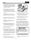
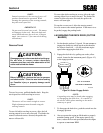
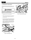
12. Dump Valve Control Levers (Figure 4-2). Located
on the hydraulic pumps, used to free-wheel the
mower. Rotating the levers clockwise until they stop
allows the unit to move under hydraulic power. The
levers must be in this position during operation of the
mower. Rotating the levers counter-clockwise allows
the mower to be moved by hand (free-wheeling).
13. Deck Lift Foot Lever (Figure 4-1). Used to raise
and lower the cutter deck.
14. Cutting Height Adjustment (Figure 4-1). Used to
set the cutter deck at the desired cutting height.
Figure 4-2 Dump Valve Control
4.2 SAFETY INTERLOCK SYSTEM
The mower is equipped with a safety interlock system
that prevents the engine from starting unless the deck
drive is disengaged, the parking brake is engaged, the
steering control levers are in the neutral position and the
operator is in the seat. The interlock system shuts off the
engine if the operator leaves the seat with the steeering
control levers not in the neutral position and/or the cutter
blades engaged and the parking brake not engaged.
Never operate the mower with the interlock
system disconnected or malfunctioning. Do not
disengage or bypass any switch; injury to
yourself and others or property damage could
result.
4.3 INITIAL RUN-IN PROCEDURES (First
Day of Use or Approximately 10 Hours)
1. Check all belts for proper alignment and wear at 2, 4
and 8 hours.
15. Deck Release Lever (Figure 4-1). Used to lock the
cutter deck in the transport position. Push the foot
pedal forward and lift up on the release lever to
release the cutter deck for normal mowing.
16. Temperature Gauge (Figure 4-1). Indicates the
operating temperature of the engine. Used on the
Kawasaki liquid cooled engine only.
WARNING:
390S0141
DUMP VALVE
CONTROL LEVER