


Section 6
20
ADJUSTMENTS
6.1 PARKING BRAKE ADJUSTMENT
WARNING:
Do not operate the mower if the parking brake is
not operable. Possible severe injury could
result.
The parking brake linkage should be adjusted whenever
the parking brake lever is placed in the ENGAGE
position and the parking brake will not prevent the mower
from moving. If the following procedures do not allow
you to engage the parking brake properly, contact your
Scag dealer for further brake adjustments.
1. Position a floor jack under the rear of the machine.
Raise the machine and support it to prevent it from
falling. Block the caster wheels to prevent the
machine from moving. Remove the drive wheels.
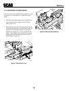
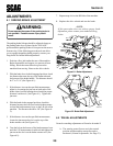
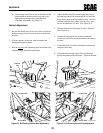
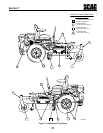
2. With the brake lever in the disengaged position, check
the distance between the top of the frame tube and
the bottom of the brake handle. The distance should
be 2" to 2-1/4" (See Figure 6-1).
3. If the distance is not at the specified measurement,
adjust by loosening the jam nuts at both ends of the
brake control rod and turning the rod until the proper
distance is achieved. (See Figure 6-1). Tighten the
jam nuts.
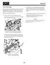
4. With the brake in the engaged position, check the
distance between the lower nut on the brake actuator
rod and the brake actuator lever on the LH side of the
machine. The distance should be 1/8" (See Figure 6-
2).
5. If the distance is not at the specified measurement,
loosen the jam nut at the clevis on the top of the
brake actuator rod (See Figure 6-2).
6. Turn the bolt at the bottom of the brake actuator lever
until the 1/8" measurement is achieved and tighten the
jam nut at the clevis on the brake actuator rod. (See
Figure 6-2).
7. Repeat steps 4-6 on the RH side of the machine.
8. Replace the drive wheels and test the brake.
-NOTE-
If this proceedure does not achieve proper brake
adjustment, please contact your authorized Scag
dealer.
6.2 TRAVEL ADJUSTMENTS
Neutral or tracking adjustments will need to be made if:
A. The steering control levers are in the neutral
position and the machine creeps forward or
backward. (Neutral Adjustment, See Page 21).
Figure 6-2. Brake Rod Adjustment
Figure 6-1. Brake Adjustment
390S0152
LOOSEN
HERE
LOOSEN
HERE
2" TO 2 1/4"
390S0153
LOOSEN
HERE
1/8"