


11
Section 4
5. Voltmeter (Figure 4-1). Indicates the condition of
the charging system. When the engine is running, in
normal operating conditions, the needle should be in
the 12 to 14 volt range.
6. Oil Pressure (Figure 4-1). Indicates engine oil
pressure. Reference the engine operator's manual
for further information.
7. Hourmeter (Figure 4-1). Indicates the number of
hours the engine has been operated. It operates
whenever the engine is running. It can be used to
keep track of maintenance intervals and the amount
of time required to perform various tasks.
8. Fuse Holders (Figure 4-1). There are two 20-
amp fuses and one 40-amp fuse that protect the
mowers electrical system. To replace fuses, pull
fuse out of the socket and install a new fuse.
9. Left Steering Control (Figure 4-1). Used to
control the mower's left wheel when traveling
forward or reverse.
10. Right Steering Control (Figure 4-1). Used to
control the mower's right wheel when traveling
forward or reverse.
11. Parking Brake Control (Figure 4-1). Used to
engage and disengage the parking brakes. Pull the
lever back to engage the parking brakes. Push the
lever forward to disengage the parking brakes.
12. Fuel Tank Gauge (Figure 4-1). Indicates the
amount of fuel in the fuel tank.
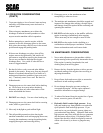
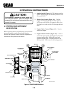
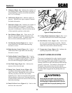
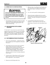
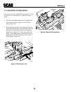
13. Dump Valve Control Levers (Figure 4-2).
Located on the hydraulic pumps, used to free-
wheel the mower. Rotating the levers clockwise
until they stop allows the unit to move under
hydraulic power. The levers must be in this position
during operation of the mower. Rotating the levers
counter-clockwise allows the mower to be moved by
hand (free-wheeling).
14. Deck Lift Foot Lever (Figure 4-1). Used to raise
and lower the cutter deck.
Figure 4-2 Dump Valve Control
15. Cutting Height Adjustment (Figure 4-1). Used
to set the cutter deck at the desired cutting height.
16. Deck Release Lever (Figure 4-1). Used to lock
the cutter deck in the transport position. Push the
foot pedal forward and lift up on the release lever to
release the cutter deck for normal mowing.
17. Temperature Gauge (Figure 4-1). Indicates the
operating temperature of the engine.
4.2 SAFETY INTERLOCK SYSTEM
The mower is equipped with a safety interlock system
that prevents the engine from starting unless the deck
drive is disengaged, the parking brake is engaged, the
steering control levers are in the neutral position and the
operator is in the seat. The interlock system shuts off
the engine if the operator leaves the seat with the
steering control levers not in the neutral position and/or
the cutter blades engaged and the parking brake not
engaged.
WARNING:
Never operate the mower with the interlock
system disconnected or malfunctioning. Do
not disengage or bypass any switch; injury to
yourself and others or property damage could
result.
390S0141BSG
DUMP VALVE
CONTROL