


13
R
Section 4
Hour meter (Figure 4-1).7. Indicates the number of
hours the engine has been operated. It operates
whenever the engine is running. Has preset
maintenance reminders for engine and hydraulic
system oil changes. Will start flashing scheduled
maintenance 2 hours before preset time and
continue flashing until 2 hours after. Automatically
resets.
Fuse Holders (Figure 4-1).
8. There are one 20-amp
fuse and one 50-amp resettable fuse that protect the
mower’s electrical system. To replace fuse, pull fuse
out of the socket and install a new fuse.
Left Steering Control (Figure 4-1).
9. Used to control
the mower's left wheel when traveling forward or
reverse.
Right Steering Control (Figure 4-1).10. Used to
control the mower's right wheel when traveling
forward or reverse.
Parking Brake Control (Figure 4-1). 11. Used to
engage and disengage the parking brakes. Pull the
lever back to engage the parking brakes. Push the
lever forward to disengage the parking brakes.
Fuel Tank Gauge (Figure 4-1)12. . Indicates the
amount of fuel in the fuel tank.
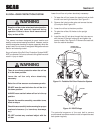
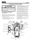
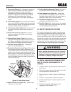
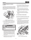
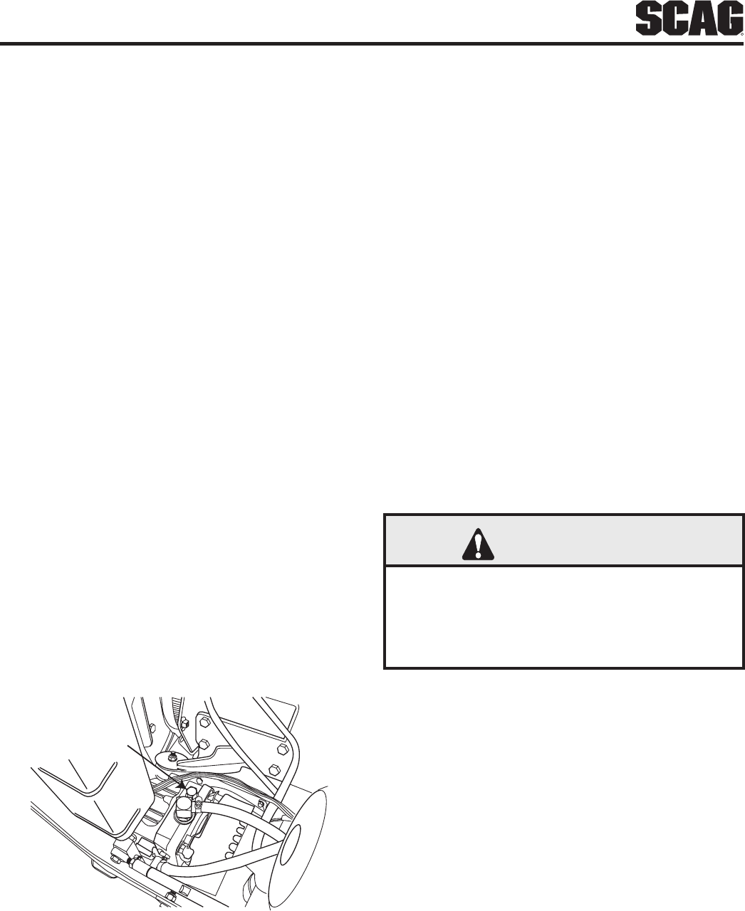
Dump Valve Control Levers (Figure 4-2). 13. Located
on the hydraulic pumps, used to “free-wheel” the
mower. Rotating the levers clockwise until they stop
allows the unit to move under hydraulic power. The
levers must be in this position and torqued to 10ft/lbs
during operation of the mower. Rotating the levers
counter-clockwise allows the mower to be moved by
hand (free-wheeling).
DUMP VALV E
CONTROL
2007 STTDVC
Dump Valve ControlFigure 4-2.
Deck Lift Foot Lever (Figure 4-1). 14. Used to raise
and lower the cutter deck.
Cutting Height Adjustment (Figure 4-1).15. Used to
set the cutter deck at the desired cutting height.
Deck Release Lever (Figure 4-1).
16. Used to lock
the cutter deck in the transport position. Push the
foot pedal forward and lift up on the release lever to
release the cutter deck for normal mowing.
Temperature Gauge (Figure 4-1).17. Indicates the
operating temperature of the engine.
Seat Belt (Figure 4-1).
18. Used to secure the operator.
Seat belt must be worn at all times when the ROPS
is in the upright and locked position.
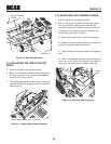
SAFETY INTERLOCK SYSTEM4.2
The mower is equipped with a safety interlock system
that prevents the engine from starting unless the deck
drive is disengaged, the parking brake is engaged, the
steering control levers are in the neutral position and the
operator is in the seat. The interlock system shuts off the
engine if the operator leaves the seat with the steering
control levers not in the neutral position and/or the cutter
blades engaged and the parking brake not engaged.
WARNING
Never operate the mower with the interlock
system disconnected or malfunctioning. Do not
disengage or bypass any switch; injury to yourself
and others or property damage could result.
INITIAL RUN-IN PROCEDURES (FIRST 4.3
DAY OF USE OR APPROXIMATELY 10
HOURS)
Check all belts for proper alignment and wear at 2, 4 1.
and 8 hours.
Change the engine oil and oil filter after the first 20 2.
hours of operation. (See Section 7.4.)
Check hydraulic oil level in reservoir. (See Section
3.
7.3.)
Check for loose hardware. Tighten as needed.4.
Check interlock system for proper operation. (See 5.
Section 4.2.)
Check tire pressure. Adjust pressure if 6.
necessary. (See Section 7.10)