


4
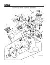
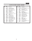
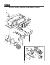
10. Install the new belt covers and secure. See items
number 1 and number 21 on page 8 of the Blower
Mounting Components section in the Illustrated
Parts List for proper installation.
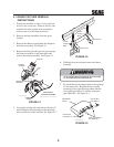
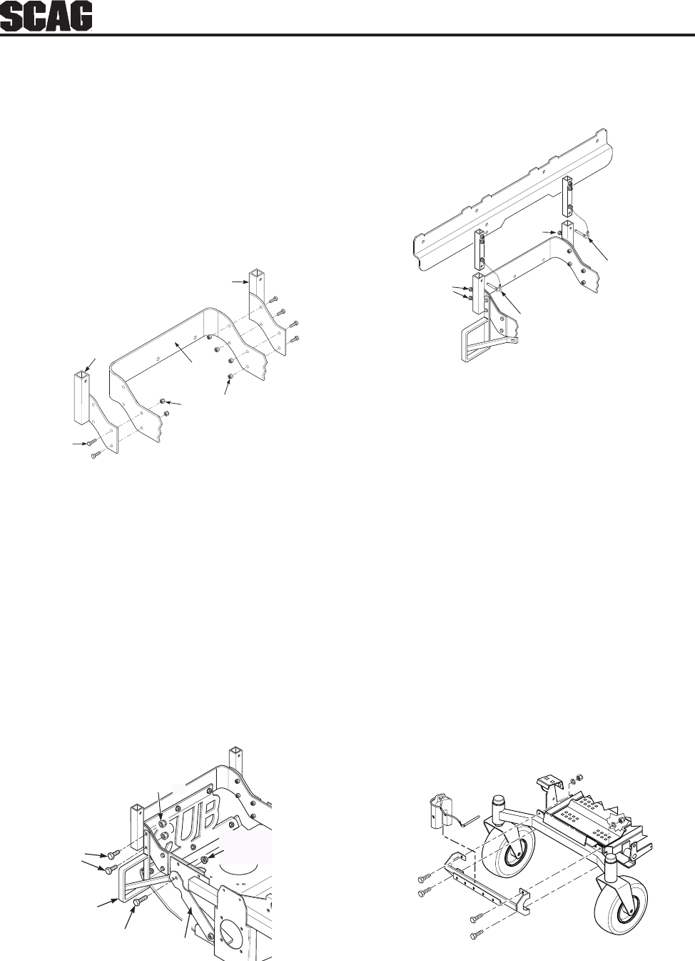
16. Using the weight support bar as a guide, identify
the four corresponding mounting holes, and the
existing hardware that will need to be removed in
order to secure the weight support bar to the front
of the machine as shown. See Figure 3-7.
17. Install one (1) 7/16-14 x 1-3/4" hex head bolt into
each of the four mounting holes in the weight
support bar, and through the matching holes in the
caster support weldment. Secure this assembly to
the front of the machine using the
7/16- .5" x 1-1/4" x .083" flatwashers, and the
7/16-14 elastic stop nuts. Torque hardware to
59 ft. lbs. See Figure 3-7.
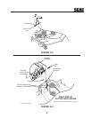
13. Attach the hood assembly to the machine by
installing the mounting post into the hopper
mounting brackets. Secure with the ring pins and
tighten the locking bolts. See Figure 3-6.
14. Install the hose from the blower assembly adapter
to the hopper hood and secure using the 6-1/2"
clamps.
15. Install the bag assemblies.
FIGURE 3-7
18. Operate and test.
FIGURE 3-6
Ring Pins
Ring Pins
Locking
Bolts
Locking
Bolts
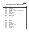
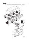
FIGURE 3-5
FIGURE 3-4
Figure 4 A 2008 GC-STT Install Art
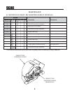
Rear Frame
LH
Hopper
Mounting
Bracket
3/8-16
Elastic Stop Nut
04021-09
3/8-16 x 1”
04001-32
RH
Hopper
Mounting
Bracket
3/8-16 x 1-1/4
04001-32
3/8-16 x 1-1/2
04001-20
3/8-16
Elastic Stop Nut
04021-09
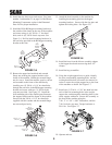
Muffler Guard
Existing
Nut
Support
Bracket
12. Remove the upper hex head bolt and serrated
flange nut securing the support bracket to the
frame of the machine. Retain the serrated flange
nut for re-use. Install the muffler guard as shown
and assemble to the frame of the machine by
installing two (2) 3/8-16 x 1-1/4" hex head bolts
through the rear holes in the RH hopper mounting
bracket and secure with two (2) 3/8-16 elastic
stop nuts provided. See Figure 3-5. Install the
front mounting tab of the muffler guard between
the support bracket and the frame of the machine.
Secure with the 3/8-16 x 1-1/2" hex head bolt
supplied with this catcher and the serrated flange
nut removed previously.
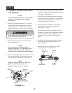
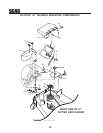
11. Install the LH & RH hopper mounting brackets to
the outside of the frame on the rear of the machine
and secure using six (6) 3/8-16 x 1" hex head
bolts, and six (6) 3/8-16 elastic stop nuts. See
Figure 3-4. Do Not install mounting hardware in
the rear holes provided in the RH hopper mounting
bracket at this time