


2
WARNING
WARNING
DO NOT OPERATE WITHOUT DISCHARGE CHUTE, MULCHING
KIT, OR ENTIRE GRASS CATCHER INSTALLED
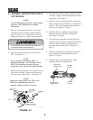
3.1 ASSEMBLY INSTRUCTIONS FOR 61"
CUTTER DECK
-NOTE-
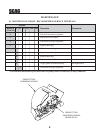
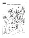
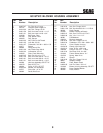
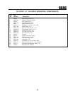
Use the illustrated parts list as a part number
reference when following the assembly
instructions.
1. Remove all packaging materials. Lay out the
mounting hardware and the catcher assembly
parts for easy access. Prepare the work area
making sure that it is a clean, safe environment.
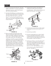
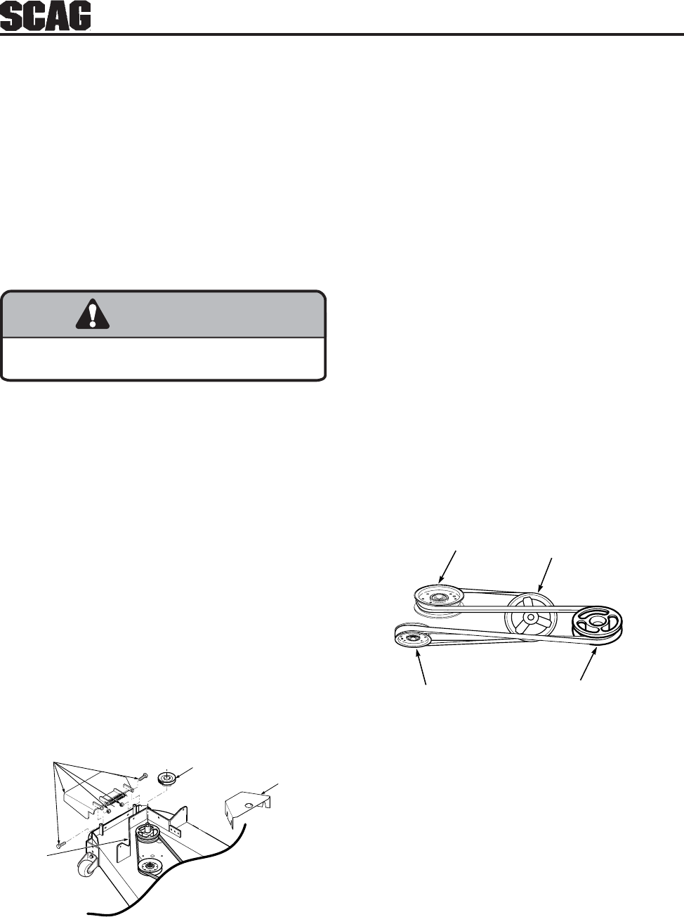
2. Remove the discharge chute from the cutter
deck. See Figure 3-1.
-NOTE-
Do not discard the discharge chute or
mounting hardware. The discharge chute
MUST be reinstalled any time the grass
catcher has been removed from the machine.
3. Remove the right side belt cover to gain access to
-NOTE-
Retain the original belt cover. This cover
MUST be reinstalled any time the
complete catcher system is removed.
the spindle assembly. Remove the front u-nut
from the cutter deck bracket. See Figure 3-1.
FIGURE 3-1
RIGHT SIDE OF
CUTTER DECK SHOWN
(Note: Some parts not shown for viewing purposes.)
REMOVE DISCHARGE
CHUTE AND
HARDWARE
REMOVE EXISTING
RT. SIDE BELT
COVER
INSTALL PULLEY
ON RH SPINDLE SHAFT -
ON TOP OF EXISTING
SPINDLE DRIVE
PULLEY
Figure 1- GC-STC install art
REMOVE U-NUT
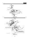
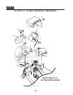
5. Install the blower mounting bracket to the deck
using carriage bolts (p/n 04003-11), lockwashers,
and nuts. Do not fully tighten the hardware at
this time. See Figure 3-2, Page 3.
6. Install the blower assembly to the mounting
bracket and secure with the mounting pin.
See Figure 3-3, Page 3.
7. Align the blower assembly with the discharge
opening of the cutter deck. Tighten the hardware
for the mounting bracket. Then tighten the
hardware for the catch plate. See Figure 3-3,
Page 3.
8. Install the large hair pin through the rear hole in
the discharge chute mounting bracket. See
Figure 3-3, Page 3.
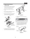
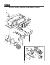
9. Install the belt to the spindle pulley. When
replacing the belt, see figure below.
4. Install the grass catcher pulley onto the spindle
assembly. Apply loctite to both pulley setscrews
and tighten. See Figure 3-1.
FRONT SIDE
IDLER PULLEY
BACK SIDE
IDLER PULLEY
BLOWER
PULLEY
SPINDLE
PULLEY