


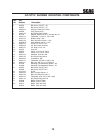
5
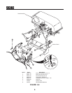
13. Install the hopper mounting brackets (p/n 451512)
to the outside of the frame on the rear of the
machine using 3/8-16 x 1" hex head bolts
(p/n 04001-19) and 3/8-16 elastic stop nuts (p/n
04021-09). See Figure 3-8, Page 6.
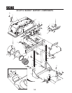
14. Install the hopper hood assembly onto the catcher
frame assembly and secure with 3/8-16 x 2-1/4"
hex head bolts (p/n 04001-46) and 3/8-16 elastic
stop nuts (p/n 04021-09) in the mounting holes.
See Figure 3-8, Page 6.
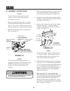
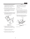
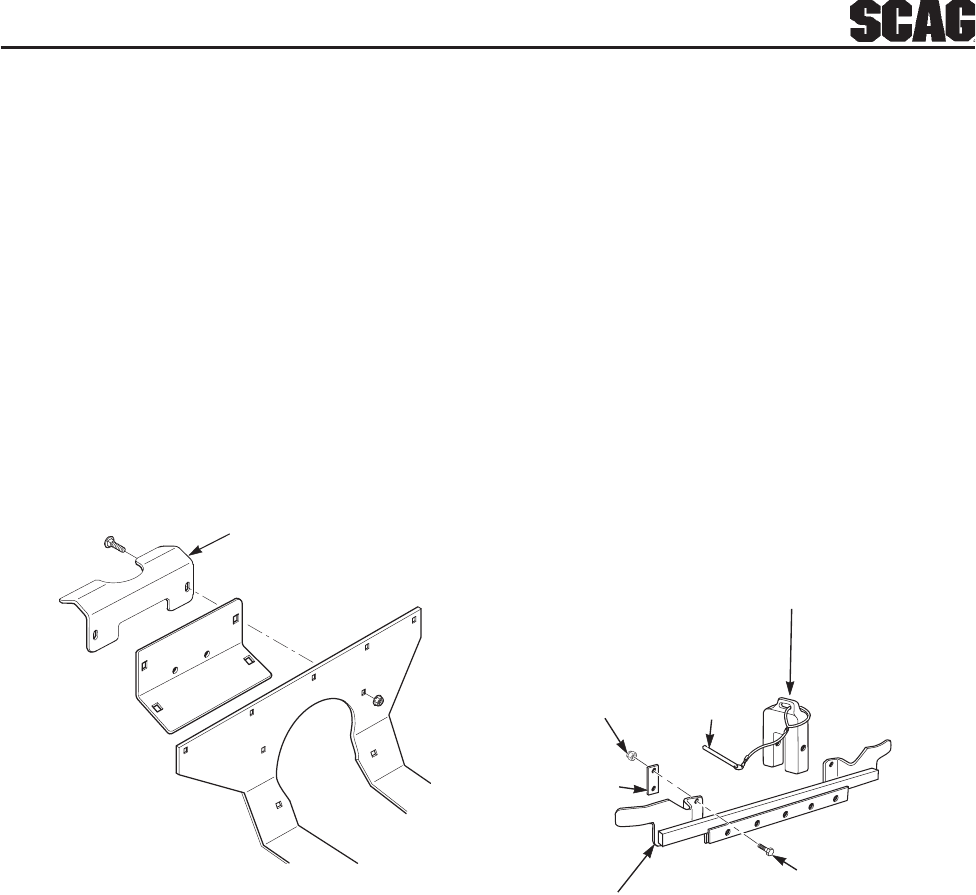
15. Install the catcher support bracket onto the rear of
the machine and secure with 5/16-18 x 1" carriage
bolts (p/n 04003-04) and 5/16-18 serrated flange
nuts (p/n 04019-03) See Figure 3-6.
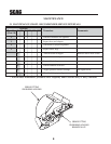
Catcher Support Bracket
FIGURE 3-6
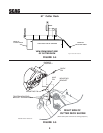
16. Install the heat shield to the hopper hood
assembly and catcher frame assembly. Secure
using the hardware specified in Figure 3-8, Page
6.
17. Install adapter (p/n 461723) to the blower
assembly and secure with the strap.
18. Install the hose from the blower assembly to the
hopper hood. Secure using the 8-1/2" clamps.
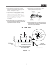
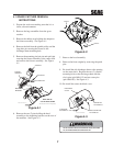
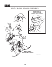
WEIGHT SUPPORT BAR
BAR CLAMP
ELASTIC STOP
NUT
WEIGHT (5x)
LANYARD
PIN
BOLT
2002 GC-STT Install Art 3-5
-NOTE-
When installing this catcher on machines
equipped with an air-cooled engine the
discharge hose should be shortened to
56" in length.
19. Install the bag assemblies.
20. Install the weight support bar to the front of the
machine by resting it directly on top of the caster
support arms and sliding it tight against the frame
of the machine. Secure the weight bar to the
machine using (2) bar clamps, (4) 3/8-16 x 1-1/2"
bolts and (4) 3/8-16 elastic stop nuts. See Figure
3-7.
21. Install the weight assemblies to the weight
support bar and secure them to the bar using the
1/2"x 6-1/4" pin and lanyard. See Figure 3-7.
21. Operate and test.
FIGURE 3-7