


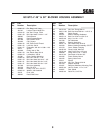

3
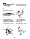
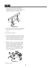
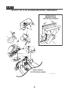
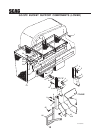
7. Install the blower assembly to the mounting
bracket and secure with the mounting pin.
See Figure 3-4.
8. Align the blower assembly with the discharge
opening of the cutter deck. Tighten the
hardware for the mounting bracket. See Figure
3-4.
9. Install the quick pin through the rear hole in the
discharge chute mounting bracket. See Figure
3-4.
FRONT SIDE
IDLER PULLEY
BACK SIDE
IDLER PULLEY
BLOWER
PULLEY
SPINDLE
PULLEY
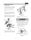
10. Install the belt to the spindle pulley. When
replacing the belt, see Figure 3-5 below.
FIGURE 3-4
11. Install the new belt covers and secure. See
items number 1 and number 21 on page 10 of the
Blower Mounting Components section in this
manual for proper installation.
FIGURE 3-5
RIGHT SIDE OF
CUTTER DECK SHOWN
(Note: Some parts not shown for viewing purposes.)
2006 GC-STC-V install art 3
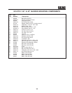
BLOWER
ASSEMBLY
MOUNTING
BRACKET
MOUNTING PIN
TIGHTEN MOUNTING
BRACKET HARDWARE
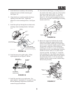
HAIR
PIN
QUICK
PIN
FIGURE 3-7
FIGURE 3-6
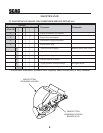
13. Remove the upper hex head bolt and serrated
flange nut securing the support bracket to the
frame of the machine. Retain the serrated flange
nut for re-use. Install the muffler guard as shown
and assemble to the frame of the machine by
installing two (2) 3/8-16 x 1-1/4" hex head bolts
through the rear holes in the RH hopper mounting
bracket and secure with two (2) 3/8-16 elastic
stop nuts provided. See Figure 3-7. Install the
front mounting tab of the muffler guard between
the support bracket and the frame of the machine.
Secure with the 3/8-16 x 1-1/2" hex head bolt
supplied with this catcher and the serrated flange
nut removed previously.
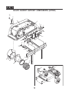
Figure 4 A 2008 GC-STT Install Art
Rear Frame
LH
Hopper
Mounting
Bracket
3/8-16
Elastic Stop Nut
04021-09
3/8-16 x 1”
04001-32
RH
Hopper
Mounting
Bracket
3/8-16 x 1-1/4
04001-32
3/8-16 x 1-1/2
04001-20
3/8-16
Elastic Stop Nut
04021-09
Muffler Guard
Existing
Nut
Support
Bracket
12. Install the LH & RH hopper mounting brackets to
the outside of the frame on the rear of the machine
and secure using six (6) 3/8-16 x 1" hex head
bolts, and six (6) 3/8-16 elastic stop nuts. See
Figure 3-6. Do Not install mounting hardware in
the rear holes provided in the RH hopper mounting
bracket at this time.