


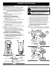
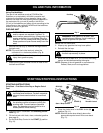
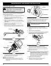

INSTALLING THE WHEEL BRACKET ASSEMBLY
WARNING: To avoid injury from the tines,
wear heavy gloves and a long sleeve shirt
when installing the wheel bracket assembly.
WARNING: To prevent serious personal
injury the wheel bracket assembly shall be
installed when operating the unit.
NOTE: The wheel bracket assembly is located in the
cardboard insert, inside at the top of the carton.
1. With the unit on it’s side, place the wheel bracket
assembly on the underside of the tine guard (Fig. 3).
2. Install a carriage bolt through each of the slotted
holes in the wheel bracket and into the tine guard.
3. On the top side of the tine guard, install a lock
washer and a wing nut onto each of the bolts (Fig. 3).
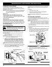
4. Make sure the square shoulder of the bolts are
through the slotted holes in the wheel bracket.
Tighten the wing nuts (Fig. 4).
NOTE: Do not over tighten the wing nuts. Loosening the
wing nuts allow the wheel height to be adjusted.
ASSEMBLING THE UNIT
Your yard and garden cultivator has been completely
assembled, except for the wheel bracket assembly.
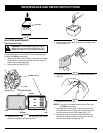
NOTE: This unit is shipped without being filled with oil.
In order to avoid damage to the unit, put oil in the
crankcase before attempting to start unit.
Unpacking
1. Carefully unpack the contents and insure that
nothing is damaged.
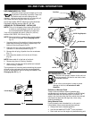
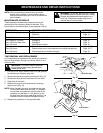
POSITIONING THE HANDLEBARS
1. Loosen the two knobs on the inside of the
handlebars (Fig. 1).
2. With the unit upright, swing the handlebars up into
the operating position (Fig. 1).
NOTE: Take care not to pinch the throttle cable or
switch wires when positioning the handlebar.
3. Remove the foam padding from between the
handlebar assembly.
4. Tighten the knobs to secure the handlebars in place.
NOTE: Do not over-tighten the knobs.
5. Readjust the throttle cable and switch wires so
they are smooth and tight against the handlebar
assembly. This will help prevent them being caught
or snagged during normal operation.
ADJUSTING THE HANDLEBAR HEIGHT
1. The height for the handlebars can be adjusted by
removing the knobs and mounting bolts and
reinstalling through either the top or bottom holes in
the handlebar assembly (Fig. 2).
2. Be sure to tighten the knobs to secure the
handlebars in place.
ASSEMBLY INSTRUCTIONS
8
Fig. 1
Fig. 2
Fig. 3
Fig. 4
Handlebar
Knobs
Handlebar
Knobs
Handlebar
Knob
Handlebars
Washer
Bottom Hole
Top Hole
Bolt
Wing Nut &
Lock Washer
Tine
Guard
Wheel
Bracket
Assembly