


6
UNPACKING
This product has been shipped completely assembled.
Carefully remove the items from the box. Make sure that
all items listed in the packing list are included.
Inspect the product carefully to make sure no breakage
or damage occurred during shipping.
Do not discard the packing material until you have care-
fully inspected and satisfactorily operated the tool.
If any parts are damaged or missing, please call
1-800-242-4672 for assistance.
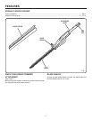
PACKING LIST
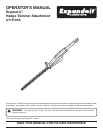
Expand-it
™
Hedge Trimmer Attachment
(Completely Assembled)
Blade Sheath
Hanger Cap
Operator’s Manual
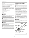
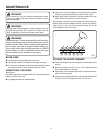
WARNING:
If any parts are damaged or missing, do not operate
this tool until the parts are replaced. Failure to heed this
warning could result in serious personal injury.
WARNING:
Do not attempt to modify this tool or create accesso-
ries not recommended for use with this tool. Any such
alteration or modification is misuse and could result in a
hazardous condition leading to possible serious personal
injury.
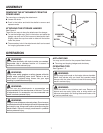
WARNING:
Do not connect to power head until assembly is complete.
Failure to comply could result in accidental starting and
possible serious personal injury.
WARNING:
Do not remove the blade sheath until the hedge trimmer
is fully assembled and ready to use. Failure to comply
could result in possible serious personal injury.
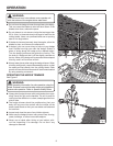
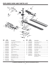
ATTACHING THE HEDGE TRIMMER
ATTACHMENT TO THE POWER HEAD
See Figure 2.
WARNING:
Never attach or adjust any attachment while power head
is running. Failure to stop the engine may cause serious
personal injury.
The hedge trimmer attachment connects to the power head
by means of a coupler device.
Loosen the knob on the coupler of the power head shaft
and remove the end cap from the attachment shaft.
Push in the button located on the hedge trimmer
attachment. Align the button with the guide recess on the
extension shaft coupler and slide the two shafts together.
Rotate hedge trimmer attachment until button locks into
the positioning hole.
Tighten the knob securely.
NOTE: If the buttons do not release completely in the
positioning holes, the shafts are not locked into place.
Slightly rotate from side to side until the button is locked
into place.
NOTE: Use only the specified positioning hole for this
attachment.
WARNING:
Be certain the knob is fully tightened before operating
equipment. Check it periodically for tightness during use
to avoid serious injury.
ATTACHMENT SHAFT
Fig. 2
ASSEMBLY
GUIDE
RECESS
POSITIONING
HOLE
KNOB
BUTTON
COUPLER
POWER HEAD
SHAFT