


Page 9
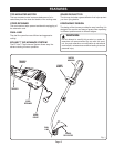
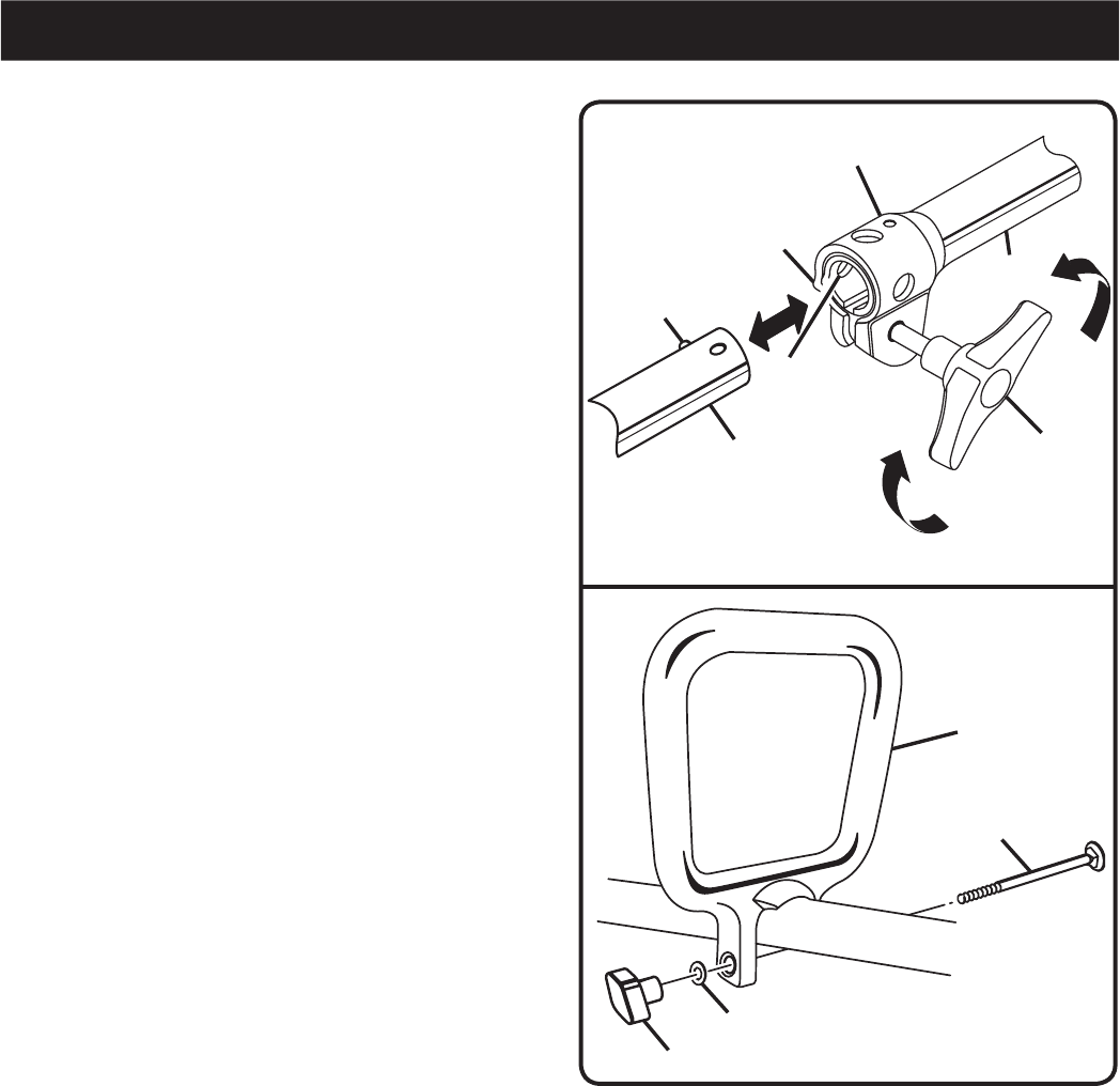
CONNECTING THE ATTACHMENT TO THE
UPPER SHAFT
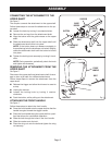
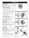
See Figure 2.
The coupler connects the attachment to the upper shaft.
Follow these steps to connect the attachment to the up-
per shaft.
n Loosen the knob by turning it counterclockwise.
n Remove the end cap from the attachment shaft.
n Align the button with the guide recess on the upper
shaft.
n Slide the attachment shaft into the upper shaft until
the attachment shaft clicks into place.
NOTE: If the button does not release completely in
the positioning hole, the shafts are not locked. Slightly
rotate the attachment shaft until the button is locked
into place.
n Tighten the locking knob securely by turning it clock-
wise.
NOTE: During operation, periodically check the knob
and tighten as necessary.
REMOVING THE ATTACHMENT FROM THE
UPPER SHAFT
See Figure 2.
Disconnect the upper shaft and attachment shaft for stor-
age or when a job calls for a different attachment.
Follow these steps to remove the attachment from the
upper shaft.
n Release the trigger and allow the trimmer to coast to
a stop.
n Unplug the trimmer.
n Loosen the locking knob by turning it counter-
clockwise.
n Push the button, while pulling out the attachment.
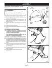
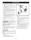
ATTACHING THE FRONT HANDLE
See Figure 3.
Follow these steps to attach the front handle.
n Press the front handle onto the upper shaft so that the
handle is angled toward the trigger handle.
n Place the front handle along the upper shaft to a posi-
tion that allows for comfortable operation.
n Slide the bolt through the holes in the front handle.
n Slide the washer onto the bolt.
n Place the wing nut onto the bolt and tighten the wing
nut securely.
Fig. 3
Fig. 2
KNOB
BUTTON
GUIDE
RECESS
UPPER
SHAFT
ATTACHMENT
SHAFT
FRONT
HANDLE
BOLT
WASHER
WING NUT
POSITIONING
HOLE
COUPLER
ASSEMBLY