


7 — English
ASSEMBLY
NOTE: The unit will not operate properly if the tines are
installed incorrectly. If you notice a problem with the cultivat-
ing operation of the unit, check for proper tine positioning.
CAUTION:
Wear heavy gloves when installing, removing, or adjust-
ing the tiller tines. With wear, the tiller tines may become
sharper.
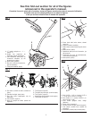
JOINING THE POWER HEAD TO THE TILLER
ATTACHMENT
See Figure 3.
The tiller attachment connects to the power head by means
of a coupler device.
WARNING:
Never attach or adjust any attachment while power head
is running. Failure to stop the engine or motor may cause
serious personal injury.
To install the attachment:
Remove the spark plug wire or disconnect from the power
supply.
Remove the hanger cap from the attachment.
Loosen the knob on the coupler of the power head
shaft.
Push in the button located on the shaft of the tiller attach-
ment.
Align the button with the guide recess on the power head
coupler and slide the two shafts together. Rotate attach-
ment shaft until button locks into the positioning hole.
NOTE: If the button does not release completely in the
positioning hole, the shaft is not locked into place. Slightly
rotate from side to side until the button is locked into
place.
Tighten the knob securely.
WARNING:
Be certain the knob is fully tightened before operating
equipment; check it periodically for tightness during use
to avoid serious injury.
To remove:
Stop the engine or motor and remove the spark plug wire
or disconnect from the power supply.
Loosen the knob.
Push in the button and twist the shafts to remove and
separate ends.
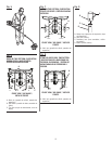
ATTACHING THE J-HANDLE
See Figure 4.
The J-handle included with the tiller attachment provides a
barrier to assist the operator in maintaining a safe distance
from the rotating tines. If the power head to which the tiller
attachment will be mounted does not have such a handle,
install the provided handle.
Hold the top and bottom clamp snugly in position on the
shaft housing so that handle will be located to the opera-
tor’s left.
Insert the end of the handle between the clamps.
Align the bolt holes and push the long bolt (1/4-20 x 1-1/2
in.) through the handle side.
Place short bolt (1/4-20 x 1 in.) through opposite side of
clamp. Install flat washers, lock washers, and hex nuts
to hold the assembly in place.
After assembly is complete, adjust the position of the
handle for best balance and comfort.
Tighten the long bolt first and then the short bolt.