


10
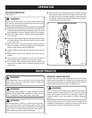
Fig. 5
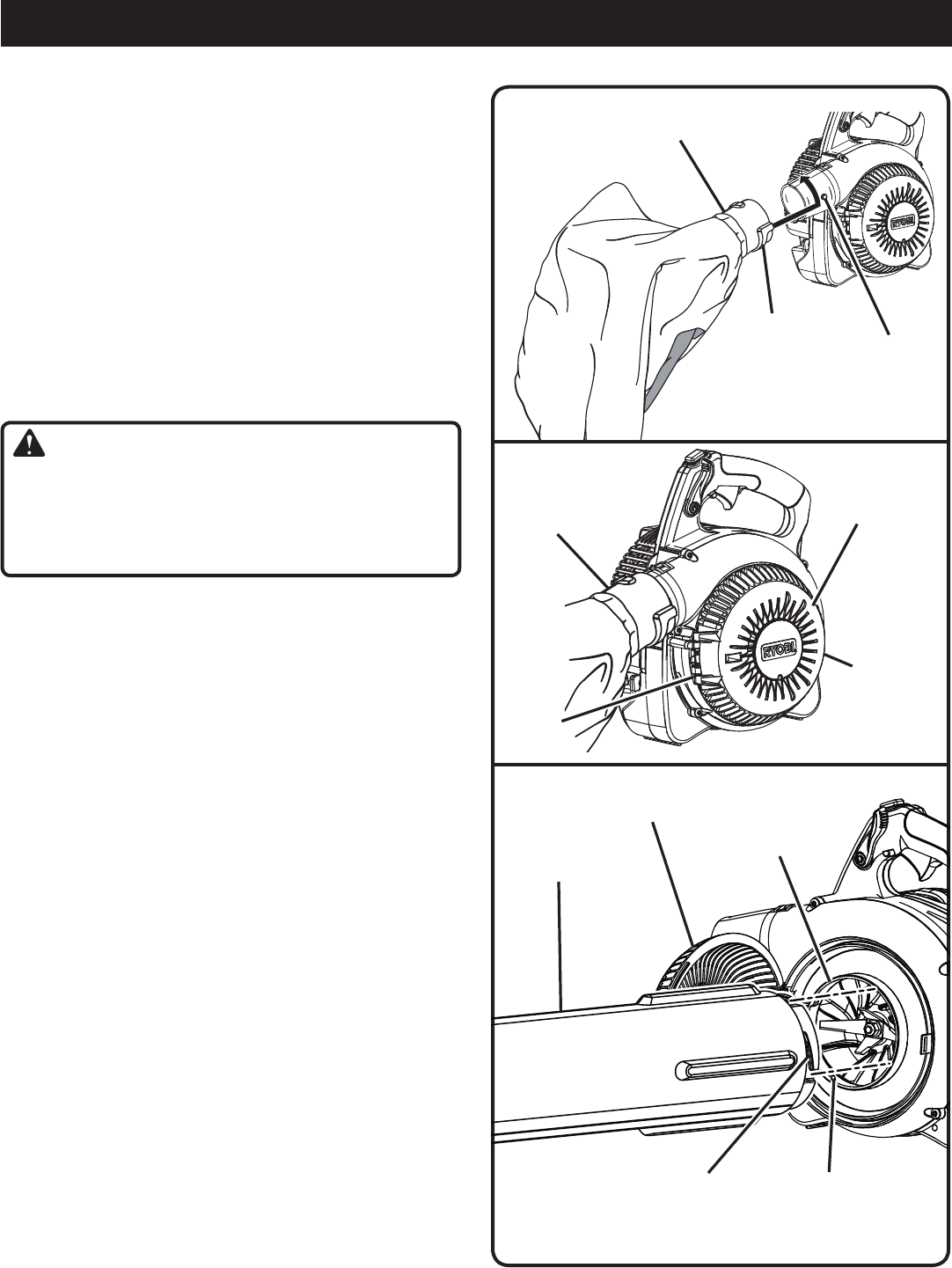
VACUUM INLET
DOOR
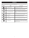
DOOR TAB
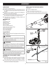
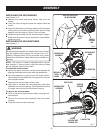
INSTALLING THE VACUUM BAG
See Figures 4 - 5.
n
Remove the nozzle and upper blower tube from the
blower.
n
Unzip the vacuum bag and place the adaptor inside as
shown.
n
Align the raised slots on the bag adaptor with the raised
locking tabs on the blower housing outlet; push the bag
adaptor onto the housing. Twist to lock into place.
n
Rotate the vacuum bag until the shoulder strap is upright.
n
Make sure the vacuum bag is zipped and closed before
starting the unit.
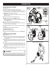
INSTALLING THE VACUUM TUBES
See Figures 6 - 7.
WARNING:
Rotating impeller blades can cause severe injury. Always
top the engine before opening the vacuum door or in-
stalling / changing tubes. Do not put hands or any other
object into the vacuum tubes while they are installed on
the unit.
NOTE: This vacuum / blower is equipped with a vacuum
door interlock. If vacuum door is open and vacuum tubes
are not installed, engine will not start.
To install the vacuum tubes:
n
Secure the upper and lower vacuum tubes together by
aligning the raised locking tabs with the raised slots.
n
Tap tube assembly on ground until the screw holes in
lower tube are in the raised slot of the upper tube. Secure
with supplied screws.
n
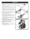
Depress door tab and open vacuum door.
n
Align tabs on housing with tube assembly. Insert tube
assembly into vacuum opening. Twist clockwise and lock
the upper vacuum tube into the blower housing.
To remove the vacuum tubes:
n
Twist to loosen the upper vacuum tube by turning coun-
terclockwise.
n
Remove the vacuum tube assembly from the blower
housing.
n
Close the inlet cover door securely.
Fig. 7
Fig. 6
VACUUM
OPENING
VACUUM TUBE
ASSEMBLY
UPPER
VACUUM TUBE
LOCKING TAB
ASSEMBLY
ADAPTOR INSTALLED
IN VACUUM BAG
RAISED
SLOT
RAISED
LOCKING
TAB
VACUUM
DOOR
HINGE
INLET DOOR
LOCKING TAB
VACUUM BAG
ASSEMBLY