


MAINTENANCE AND REPAIR INSTRUCTIONS
13
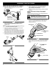
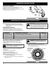
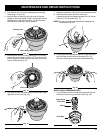
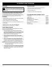
Line Locking Hole
Trimming Line
Line Loading Hole
Eyelet
5. Insert the line into the locking hole (Fig. 15). Do not
push the line more than 1/2 inch (12.7 mm.) into the
line locking hole. When inserted correctly the line will
form a small loop (Fig. 15).
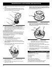
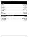
6. Pull the line from the outer spool until the line is tight
against the inner reel (Fig. 16).
3. Pull old line out of the line loading and line locking
holes (Figs. 14 and 15).
4. Insert a piece of trimming line into one of the two
eyelets in the outer spool. Push it up through the line
loading hole in the inner reel (Fig. 14). Do not bend
the line when inserting it into the eyelet.
Fig. 14
Fig. 16
Fig. 15
9. If winding the line becomes difficult or the line jams,
pull the ends of the line from the spool (Fig. 18).
Continue winding the inner reel counterclockwise .
7. Repeat procedures 4-6 with the second piece of line.
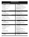
8. Hold the outer spool. Wind the inner reel
counterclockwise until approximately four (4) inches
(102 mm.) of line remain (Fig. 17).
NOTE: Do not wind the inner reel before installing the
second piece of line.
Fig. 17
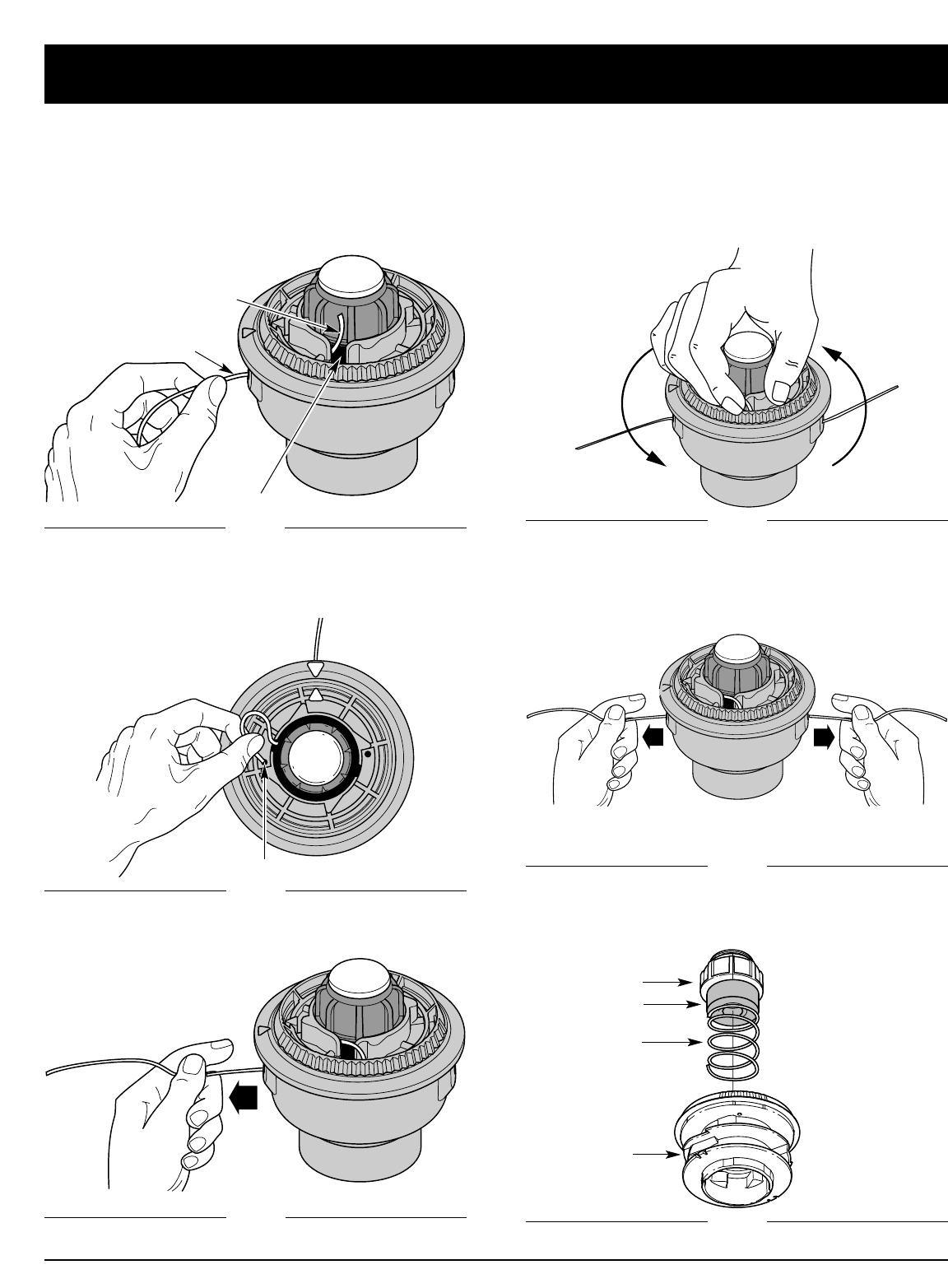
Fig. 18
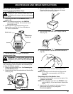
Bump Knob
Foam Seal
Spring
Inner Reel
INSTALLING A PREWOUND REEL
1. Turn the Bump Knob counterclockwise and remove
the bump knob, spring, and foam seal (Fig. 19).
Fig. 19