


1 4
2 5
3 6
i
A
B
A
B
A
PAGE 11
Rover Mowers Limited
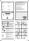
GB Self propelled drive control
Moved towards (I) turns the clutch on and drives the mower forward.
Moved towards (O) turns the clutch off and stops the mower
driving
D Selbetantriebbetätgung
Einstellung auf (I) aktiviert die Kupplung und den Motor vorwärs.
Einstellung auf (I) schaltet die kupplung aus und bringt den Mäher zum
Stehen
F Contrôle d'autotraction
Déplacé vers (I) enclenche l'embrayage et fait avancer la tondeuse.
Déplacé vers (O) décengage l'embrayage el empéche la tondeuse d'avancer
SP Autopropulsado marcas del control
Movido hacia (I) mueve el desembragador y pone a marcha el cortacesped.
Movido hacia el (O) apaga el desembragador y para el cortacesped
NL Regulatuur bij relfverplaatsende machines
Als men de knop op (I) zet, is de koppeling ingeschakeld en de machine
rijdt vooruit. Als de knop (O) zet, schakelt men de knoppeling uit en
de machine stopt.
I Camando trazione removente
Se mosso verso I (innestato) innesta la frizione e muove in avanti la
faiciatrice tosaerba. Se mosso verso O (disinnestato) disinnesta la
frizione e ferma la trazione della falciatrice tosaerba
GB Operator presense control
Handle moved towards the handle bars, engine and blades are free to
rotate. Handle released, engine and blades stop rotating
D Bedieneranwesenheitakontrolle
Giff in Richtung Giffbügel vorgestzt, motor und messer rotieren frei,
Griff gelôst, Motor und messer stoppen
F Contrôle par opérateur
Poigée avancée vers les mancherons, moteur et lames peuvent tourner.
Poignée relâchée, moteur arrêtent de tourner
SP Operador de las presencias controles
Mango movido hacia manillas, motor y cuchillas estanlibres de hacer
vucltas. Mango disparado, motor y cuchillas paran de hacer vucltas
NL Dodenmanskoop regulatuurknop die aangeeft dat de oparateur
aanwezig is
De gasbedieningshendel geplaast in de richting van de hand grepen,
de machine loopt en de messen draaien vrij. Gasbedieningshendel is
afgezet, de machine stopt, en de messen draaicn neit meer
I Comando presenza operatore
(I) Manopola mossa verso barre manubrio, motere e lame in posizione
libers e rptanti. (O) manopola disimpegnata. Motre e lame fermi
GB Throttle control
Marked for off, slow and fast positions
D Gasbedienung
Markierung aus, langsam sch schnell
F Contrôle des gaz
Marque pour les positions arrêt, ralenti accéléré et
SP Control del accelerador
Marcado por apagado, despacio, rapido posiciones
NL Gasknop regulatuur
Voorzien van markteken uit, langzaam, snel tekening
I Comande
Segno di poizione O staccato lento veloce
3632 Steel Export.PMD 11/11/2002, 10:10 AM2
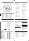
Rover Mowers Limited 7. SPARE PARTS
1 A03802 Upper handle bars-Mod 60
2 A10016 Throttle control assembly
3 A03581 Throttle cable- Quantum
4 A03557 Key start housing
5 A03560 Key start switch
6 A07679 Ignition key
7 A03741 Wiring loom- Mod 60 CE
8 A03565 Cable clamp
9 A03559 Battery
10 A03558 Battery block
11 A03556 Battery support box
12 A03563 Decal- caution
13 A02083 Setscrew- 5/16" x 3/4" unc.hex.
14 A02012 Washer- 5/16" x 7/8" x 18g.flat
15 A02223 Nyloc nut- 5/16" unc.
16 A02002 Speed nut- 3/16" bsw.
17 A02163 Screw- 3/16" x 1/2" mush/head
18 A04060 Rivet- 73 AS 5-2
19 A03610 Foam block
20
21 A10524 Bale assembly- Mod 60 CE
22 A10503 Handle assembly Mod.60- CE
23 A02521 Spacer
24 A03739 Handle grip- CE
25 A03732 Cable clip- CE
26 A03733 Rope stop- CE
27
28 A02235 Nyloc nut- 1/4" unc.
29 A04083 Screw- 10 x 3/4 pan head
30
30 A03722 Brake cable- mod. 60
31 A03756 Switch Plate
7.4 Powerstart spare parts - Series 85000, 86000
PAGE 9
Rover Mowers Limited ENGLISH PREFACE
WARNING
CAUTION
Follow these instructions to avoid mower damage and
possible loss of warranty
The safety of the user and others involved. Personal Injury
may result should this information be disregarded.
CONTENTS PAGE
Preface ............................................................................iii
Safety Instructions ..........................................................iv
1. Setting up................................................................... 1
1.1 Grass catcher assembly ................................... 1
2. Before operating ........................................................ 1
2.1 Folding handles ............................................... 1
2.2 Handle bar height ............................................ 1
2.3 Engine lubrication ........................................... 1
2.4 Fuel.................................................................. 1
2.5 Controls ........................................................... 1
3. Operation ................................................................... 1
3.1 Grass catcher ................................................... 1
3.2 Adjusting the height of cut .............................. 1
3.3 To start the engine ........................................... 1
3.4 To stop the engine ........................................... 1
3.5 Self propelled mowers..................................... 1
3.6 Blade brake control ......................................... 1
4. Maintenance - General .............................................. 2
4.1 Engine air cleaner ............................................2
4.2 Snorkel air cleaner........................................... 2
4.3 Spark Plug .......................................................2
4.4 Cutting assembly .............................................2
4.5 Blade change ................................................... 2
4.6 Throttle control................................................ 2
5. Maintenance - self propelled mowers........................ 2
5.1 Drive chain lubrication ....................................2
5.2 Drive chain adjustment.................................... 2
5.3 Rear drive chain inspection .............................3
5.4 Clutch adjustment............................................ 3
5.5 Clutch lining inspection .................................. 3
5.6 Drive pawl lubrication..................................... 3
5.7 Drive Wheel Cleaning .....................................3
6. Maintenance powerstart mowers
6.1 Battery removal ............................................... 3
6.2 Battery installation .......................................... 3
6.3 Battery charging .............................................. 3
6.4 Care and handling............................................ 3
7. Spare parts ................................................................. 6
7.1 Series 85000, 86000, 96000 base .................... 6
7.2 Series 85000, 86000, 96000 bars .................... 7
7.3 Self-propelled ..................................................8
7.4 Powerstart........................................................ 9
ILLUSTRATIONS ................................................. PAGE
Figure 1. Grass catcher assembly ...............................i
Figure 2. Handle bar height adjustment .....................i
Figure 3. Throttle control markings ........................... i
Figure 4. Operator presence control ...........................i
Figure 5. Self propelled drive control ........................ i
Figure 6. Grass catcher fitment ..................................i
Figure 7. Height adjustment ......................................ii
Figure 8. Blade bolt assembly ...................................ii
Figure 9. Drive chain cover plate ..............................ii
Figure 10. Drive chain.................................................ii
Figure 11. Drive shaft cover........................................ii
Figure 12. Stone cover ................................................ii
Figure 13. Clutch adjustment ......................................ii
Figure 14. Drive wheel................................................ii
Figure 15. Drive pinion ...............................................ii
Figure 16. Powerstart control ......................................ii
iii
Thank you for buying a Rover Product. All Rover Lawn mowers are designed and constructed to give optimum grass cutting
performance under normal grass cutting conditions.
This manual covers the operation and maintenance of the Rover walk behind mower. Please read and understand this owners
manual, before using the mower.
If any point is unclear, contact Rover Mowers Limited or any authorised Rover Mower service dealer.
Rover Mowers Limited reserves the right to make changes of, and add improvements upon, its product at anytime, without notice
or obligation. The Company also reserves the right to discontinue manufacture of any product at its discretion at any time.
To emphasise special information, the words WARNING and CAUTION are used.
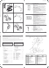
Rover Mowers Limited 7. SPARE PARTS
1 A03300 Base 1
2 A03510 Height adjustment rack 1
3 A03456 Rear Flap 1
4 A03325 Spring- rear flap 1
5 A03455 Handle- rear flap 1
6 A03126 Pivot bush 2
7 A10148 Conbar assembly 1
8 A02591 Conbar spring 1
9 A03515 Axle bracket- RH. 1
10 A03514 Axle bracket- LH. 1
11 A03516 Clamp bolt 2
12 A02051 Woodruff key 1
13 A01486 Disc boss 1
14 A00293 Disc assembly 1
15 A01716 Backplate 1
16 A03830 Blade- standard 4
16 A03930 Blade- Mulch N Catch
17 A00673 Blade bolt kit 2
18 A10154 Disc bolt kit 1
19 A10140 Front axle assembly- professional 1
19 A10527 Front axle assembly- professional 1
20 A03450 Front axle bush 2
21 A03459 Wheel seal 4
22 A03320 Front wheel assembly 2
23 A03353 Wheel bearing 8
24 A03414 Wheel cap 4
25 A03306 Pivot rod 1
26 A03743 Decal- Warning 1
27 A03492 Decal- sound level 1
28 A03409 Nameplate 1
29 373109 Tension washer 4
30 A03092 Ratchet plate 4
31 S2501116 Ratchet plate 2
32 290112 Poprivet- 73 AS 6-4 blind 10
33 A02127 Taptite- 3/8" - 16 HWH x 1" Ind.hex.W/H Duo. 3
34 * Decal- Model 1
35 A04052 Self tapping screw- 10 x 5/8" pan ph/head2
36 A03549 Cable clip 1
37 A03323 Plug chain slot- model 50 1
38 A010141 Rear axle assembly- model 50 1
39 A03313 Rear axle bush- model 50 2
40 A03250 Plastic handle 1
41 A10284 Height adj. lever assembly 1
42 A03336 Packing plate 1
43 A02066 Rivet 2
44 A03319 Rear wheel assembly 2
45 A03303 Grass deflector 1
46 A10381 Rear stoneguard- Mod. 50 1
46 A03604 Rear stoneguard- Mod. 60 1
47 A02071 Rivet- 73 SS 4-3 2
48 A02235 Nyloc nut- 1/4" unc. 2
49 A03472 Decal- turbothrust 1
50 A03927 Nose comb 1
51 A04108 Rivet 2
52 A04099 Washer- 3/16" x 3/4" 2
53 A04111 Screw 2
7.1 Series 85000, 86000 and 96000 base spare parts
PAGE 6
26
Rover Mowers Limited ENGLISH 4. MAINTENANCE GENERAL
5. MAINTENANCE - Self propelled mowers
5.1 Drive chain lubrication
1. Remove the spark plug lead.
2. Remove the cover plate screws (a) and lift off the cover plate (b).
Figure 9.
3. Support the rear wheels off the ground to enable the drive to be
rotated.
4. Use SAE 30 oil and lubricate the drive chains at point (a) whilst
the chain is being rotated. Figure 10.
5. Replace the chain cover plate and secure.
6. Replace the spark plug lead.
5.2 Drive chain adjustment
Front drive chain
1. Remove the spark plug lead.
2. Remove the cover plate.
3. Loosen the chain tensioner bolt (b) and move the chain tensioner to
give a 3 mm deflection on the drive chain. Figure 10.
4. Tighten the chain tensioner bolt and rotate the drive wheels to check
the drive chain for tight spots.
5. Replace the cover plate.
Rear drive chain
1. Remove the spark plug lead.
2. Loosen the rear drive chain tension nut (c) and slide it upwards to
tighten the rear drive chain. Figure 9.
3. Retighten the rear drive chain tensioner nut and rotate the rear drive
wheels to check for tight spots.
4. Replace the spark plug lead.
5.3 Rear drive chain inspection
1. Remove the spark plug lead.
2. Remove the drive shaft cover plate retaining screws (a) and remove
cover plate (b). Figure 11.
3. Remove the stone guard retaining screws (c) and remove the stone
guard. Figure 11.
4. Remove the chain guard nuts (d) and slide the chain guard out of the
way. Figure 12.
5. Inspect the drive chain and axle sprocket and replace if found to have
excessive wear.
6. Replace the stone guard and drive shaft axle plate.
7. Replace the spark plug lead.
5.4 Clutch adjustment
1. Remove the spark plug lead.
2. Loosen the locknut (a) and turn the adjuster (b) clockwise until the
clutch is felt to drag. Figure 13.
3. Back off the adjuster anti-clockwise 2-3 turns and retighten locknut
(a).
4. Replace the spark plug lead.
4.1 Engine air cleaner
Refer to the engine manufacture's instructions for detailed cleaning
instructions.
The engine air cleaner element must be serviced after each 25 hours of
normal mowing. The element must be serviced more regularly if the
mower is used in dusty conditions.
4.2 Snorkel air intake
The snorkel air cleaner element must be serviced after each 50 hours of
normal mowing. The element must be serviced more regularly if the
mower is used in dusty conditions.
1. Disconnect the air tube from the element holder.
2. Remove the holder cap.
3. Remove the cartridge and tap gently on a flat surface to remove dirt.
4. Replace element in holder and replace holder cap.
5. Replace the air tube to the bottom of the element holder.
NOTE: Quantum engines fitted with a Remote snorkel air
intake are not fitted with an air cleaner element. Note the
air cleaner element on this model is located on the engine.
CAUTION
Do not allow dirt to enter the air tube, engine damage may occur.
Check the condition of the air tube regularly and replace if
damaged.
4.3 Spark plug
For best results remove and check the condition of the spark plug every
25 hours of use.
1. Stop the engine and remove the spark plug lead.
2. Clean dirt from around the spark plug and remove the spark plug.
3. If a new spark plug is required use a Champion RJ19LM or
equivalent and set the electrode gap at 0.7 to 0.8 mm.
4. Screw the spark plug into the engine and tighten to 20NM.
4.4 Cutting assembly
1. Disconnect the spark plug lead.
2. Move the height of cut lever to the high cut position, and fold the
handle bars.
3. Tilt the mower so that the spark plug is up.
4. Inspect the cutting assembly for damage and wear.
5. Check the disc retaining bolts. Tighten the centre bolt to 48 Nm.and
the three concentric bolts to 14 Nm.
6. Return mower to its normal position and replace the spark plug lead.
WARNING
Remove the spark plug lead before working on cutting assembly.
Do not work on the cutting assembly without wearing gloves.
4.5 Blade change
1. Disconnect the spark plug lead.
2. Set the mower to the high cut position.
3. Lift the rear flap on rear catcher mowers and prop open the flap to
give access to the blades.
Tilt utility mowers so that the spark plug is up.
4. Remove the blade, blade retaining bolts, nuts and washers and
discard. Retain only the ‘D’ plates.
5. Fit new blades, blade bolts, washers, and nuts in sets to maintain
balance. Figure 8.
6. Tighten the blade nuts to 16 NM. Check the blades are free to move
when the blade nut is tensioned.
7. Remove the flap prop or lower the mower to the ground and replace
the spark plug lead.
4.6 Throttle control
Each 25 hours of mowing use a small amount of light oil to lubricate
the throttle control lever.
Page 2
CAUTION
Do not over tighten the spark plug as engine damage may occur.
Rover Mowers Limited 7. SPARE PARTS
PAGE 8
1 A02102 Washer- Avdel 7601/0010
2 A10177 Clutch lever
3 A03365 Clutch cable
4 A07822 Cable tie
5 A03314 Rear axle support
6 A03391 Stoneguard mount bracket
7 A03383 Rear stoneguard- 96012
7 A10381 Rear stoneguard- 86012, 86040
8 A03393 Drive shaft cover
9 A02090 Circlip- 1400/12
10 A03373 Pawl retainer washer
11 A03371 Drive pinion- RH
12 A03372 Pawl
13 A03361 Bearing- 6001 DDU
14 A07675 Nylon bush
15 A10172 Rear axle assembly
16 A03366 Rear chain guard
17 A03394 Felt seal
18 A02069 Roll pin- 1/8" x 3/4"
19 A03368 Rear drive shaft sprocket
20 A03382 Dust seal
21 A03353 Wheel bearing
22 A03352 Geared wheel hub
23 A03441 Washer plate
24 A03414 Wheel cap
25 A03369 Drive shaft
26 A03377 Rear drive chain
27 A03364 Cable support bracket- RH
28 A03367 Chain tensioner
29 A03360 Clutch engagement bush
30 A10171 Driver clutch plate
31 A03358 Clutch spring
32 A10170 Driven clutch plate
33 A03359 Clutch support shaft
34 A03550 Drive chain housing- LH
35 A03363 Cable support bracket- LH
36 A03370 Drive pinion- LH
37 A04052 Self tapping screw- 10 x 5/8" pan ph/head
38 A03552 Chain guard cover plate
39 A03551 Drive chain housing- RH
40 A03386 Felt seal
41 A02070 Roll pin- 3/16" x 7/8"
42 A03354 Sprocket PTO.
43 A03376 Front drive chain
44 A03375 Pivot rod
45 A03250 Handle
46 A02146 Setscrew- 1/4" x 3/4" unc.hex
47 A02214 Setscrew- 1/4" x 5/8" unc.hex
48 A02078 Setscrew- 1/4" x 1/2" unc.hex
49 A02081 Setscrew- 1/4" x 1-3/4" unc.hex
50 A02235 Nyloc nut- 1/4" unc.
51 S2491162 Nut- 1/4" unc.square pressed
52 A02001 Nut- 1/4" unc.hex
53 A03092 Washer- Avdel 7301/0016
54 A02030 Washer- 5/16" x 5/8" x 18g.flat
55 A02209 Washer- 1/4" x 5/8" x 18g.flat
56 A02044 Washer- 1/4" internal shakeproof
57 S373109 Tension washer
58 A10146 Wheel assembly
59 S2501108 Washer- Avdel 7301/0008
60 A10284 Height adjustment lever assembly
61 A02118 Rivet- 3/4" x 1/4" flat head
62 A03336 Plate
63 S3521047 Wheel plug
64 A03470 Chain guide
65 290112 Rivet- 73 AS 6-4 blind
66 A03390 Clutch plate lining
67 A03384 Tyre
68 A10524 Bale assembly CE
69 A10503 Handle assembly CE
70 A03739 Handle grip CE
71 A02521 Spacer CE
72 A03604 Rear extension- Mod. 60
7.3 Self propelled spare parts
Rover Mowers Limited ENGLISH SAFETY INSTRUCTIONS
Safety Instructions
1. Training
a. Read the instructions carefully. Be familiar with the
controls and the proper use of the equipment.
b. Never allow children or people unfamiliar with these
instructions to use the mower. Local regulations may
restrict the age of the operator.
c. Never mow while people, especially children, or pets
are nearby.
d. Keep in mind that the operator or user is responsible
for accidents or hazards occurring to other people or
their property.
2. Preparation
a. While mowing, always wear substantial footwear and
long trousers.
Do not operate the equipment when barefoot or
wearing open sandals.
b. Thoroughly inspect the area where the equipment is
to be used and remove all stones, sticks, wires,
bones and other foreign objects.
c. WARNING- Petrol is highly flammable.
Take the following precautions.
i. Store fuel in containers specially designed for this
purpose.
ii. Refuel outdoors only and do not smoke while
refuelling.
iii. Add fuel before starting the engine. Never remove
the cap of the fuel tank or add petrol while the engine
is running or when the engine is hot.
iv. If petrol is spilled, do not attempt to start the
engine but move the machine away from the area of
spillage and avoid creating any source of ignition
until petrol vapours have dissipated.
v. For reasons of safety the petrol tank and tank cap lock must be
replaced if damaged.
d. Replace faulty silencers.
e. Before using, always visually inspect to see that the
blades, blade bolts and cutter assembly are not worn or
damaged. Replace worn or damaged blades in sets to
preserve balance.
f. On multibladed machines, take care as rotating one
blade can cause other blades to rotate.
3. Operation
a. Do not operate the engine in a confined space where
dangerous carbon monoxide fumes can collect.
b. Mow only in daylight or in good artificial light.
c. Avoid operating the equipment in wet grass, where
feasible.
d. Always be sure of your footing on slopes.
e. Walk, never run.
f. For wheeled rotary machines, mow across the face of
slopes, never up and down.
g. Exercise extreme caution when changing direction on
slopes.
h. Do not mow excessively steep slopes.
i. Use extreme caution when reversing or pulling the
mower towards you.
j. Stop the blade(s) ,if the mower has to be tilted for
transportation when crossing surfaces other than grass
and when transporting the mower to and from the area
to be mowed.
k. Never operate the mower with defective guards or
shields, or without safety devices, for example deflectors
and/or grass catchers in place.
l. Do not change the engine governor settings or overspeed
the engine.
m. Disengage all blade and drive clutches before starting
the engine.
n. Start the engine or switch on the mower carefully
according to instructions and with feet well away
from the blade(s).
o. Do not tilt when starting the engine or switching on
the motor, unless the mower has to be tilted for
starting. In this case, do not tilt it more than absolutely
necessary and lift only the part which is away from the
operator.
p. Do not start the engine when standing in front of the
discharge chute.
q. Do not put hands or feet near or under rotating parts.
Keep clear of the discharge opening at all times.
r. Never pick up or carry a mower while the engine is
running.
s. Stop the engine and disconnect the spark plug lead:
i. Before clearing blockages or unclogging the chute.
ii. Before checking, cleaning or working on the mower.
iii. After striking a foreign object. Inspect the mower for
damage and make repairs before restarting and
operating the mower.
iv. If the mower starts to vibrate abnormally check
immediately.
t. Stop the engine
i. Whenever you leave the mower.
ii. Before refuelling.
u. Reduce the throttle setting during engine run-out and if
the engine is provided with a shut-off valve, turn off the
fuel at the conclusion of mowing.
4. Maintenance and storage.
a. Keep all nuts, bolts, and screws tight to be sure the
equipment is in safe working condition.
b. Never store the equipment with petrol in the tank inside
a building where fumes may reach an open flame or
spark.
c. Allow the engine to cool before storing in any enclosure.
d. To reduce the fire hazard, keep the engine, silencer,
battery compartment and petrol storage area free of
grass, leaves, or excessive grease.
e. Check the grass catcher frequently for wear or
deterioration.
f. Replace worn or damaged parts for safety.
g. If the fuel tank has to be drained, do this outdoors.
iv
3632 Imposed PDF's.indd 3 18/05/2006 2:36:10 PM