


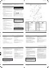


Rover Mowers Limited ENGLISH 1. SETTING UP
3. Press firmly down on the catcher top to lock the barbs into slots.
Figure 1.
4. Secure with two screws provided.
2. BEFORE OPERATING
2.1 Folding handles
l. Locking knobs- By turning these knobs the handle bars can be either
locked in the operating position or folded for storage.
2. Locking lever- Lift the lever to release the handle bars for folding
or push the lever closed to lock handle bars in the operating position.
Adjust the tension by turning the lock nut with a 1/2" AF
spanner.
2.2 Handle bar height
1. Loosen the two nuts (A) at the base of the handle bars on both sides
of the mower using a 1/2" AF spanner. Figure 2.
2. Move the handle bars to the required position and tighten the handle
bars nuts.
2.3 Engine lubrication
The engine oil level must be checked before attempting to start the engine.
Refer to the engine manufacturer's instructions.
1. Position the mower on a level surface and clean around the dip stick
or oil plug.
2. Remove the dip stick or oil plug.
3. Using a clean funnel slowly add oil in accordance with the engine
manufacturer's instructions.
4. Check the oil level by screwing in the dip stick or oil plug and
removing again. When oil level is correct replace the dip stick.
CAUTION
Avoid premature engine failure by using a clean funnel
and clean away any possible contaminants.
2.4 Fuel
1. Position the mower on a level surface in a well ventilated area and
clean around the fuel tank cap.
2. Using a clean funnel fill the fuel tank with unleaded petrol.
3. Replace the fuel tank cap and clean away any spilt petrol.
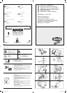
2.5 Controls
Throttle Control
Marked for O (off)
(slow) (fast) positions. Figure 3.
Operator Presense Control
Handle moved towards the handle bars (I). Engine and blades are free to
rotate. Handle released (0) engine and blades stop rotating. Figure 4.
Self Propelled Drive Control
Moved towards 1 (on) turns the clutch on and drives the mower forward.
Moved towards O (off) turns the clutch off and stops the mower driving.
Figure 5.
Powerstart
Turn the key to on (I) position to engage the electric starter. release the key
when the engine starts and allow to return to the off (0) position. Figure
16.
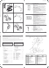
3.1 Grass catcher
Installing the grass catcher
1. Raise the rear flap of the mower.
2. Grasp the grass catcher by the top handle and position the grass
catcher against the rear of the mower. Figure 6.
3. Lower the rear flap so that the back edge of the flap hooks over the
grass catcher.
Removing the grass catcher
1. Grasp the grass catcher top handle and lift up.
2. Raise the rear flap of the mower to release grass catcher.
3. Lift the grass catcher clear of the mower and lower the rear flap.
3.2 Adjusting the height of cut
1. Grasp the height of cut lever (A) and apply an outward pressure to
release the lever from the rack (B). Figure 7.
2. Move the lever while holding out to the required height of cut
position and engage the lever in the rack by releasing the lever.
3.3 To start the engine
1. Move the Throttle Control lever to the fast position.
2. Press the primer bulb firmly 5 times.
3. Grasp the 'Operator presence control handle' and hold against the
handle bars. Refer engine manufacturers instructions. Fig. 4.
4. Grasp the starter handle and pull, or turn the ignition key on
Powerstart mowers.
5. After engine starts, move the Throttle Control to the slow position.
CAUTION
With powerstart mowers if the engine fails to start after 3
seconds of continuous cranking release the ignition key and
wait 10 seconds before trying to restart the engine. If the engine
still fails to start check the fuel level, battery connections, and
battery condition. If the engine is cranking slowly the battery
may need charging, refer to section 6.3 for battery charging.
3.4 To stop the engine
1. Move the throttle control lever to the stop position. O
2. Release the “Operator presence control handle”.
3. Turn the fuel tap off where fitted.
4. Remove the ignition key on Powerstart mowers.
3.5 Drive engagement - Self propelled mowers
1. Start the engine and set the engine speed to the required grass cutting
speed.
2. Push forward on the clutch engagement lever to engage the self-
propelled drive to the rear wheels. Fig. 5.
3. To disengage the self-propelled drive release the engagement
lever and allow it to return to the disengaged position.
CAUTION
Do not hold the engagement lever in a semi-engaged position to
slip the clutch as this will lead to excessive clutch wear.
3.6 Blade Brake Control
The mower engine is fitted with a blade brake system. When the
“Operator Presence Control” is held against the handle bars the brake is
off (0). When the Operator presence control is released the blade brake is
on (I).
1.1 Grass catcher assembly
1. Locate the catcher handle and align its front lugs with the slots
in the top of the catcher and press firmly into position. Figure 1.
2. Position the catcher top over the catcher bottom, aligning the barbs
on the top with the slots in the bottom. Figure 1.
3. OPERATION
Page 1
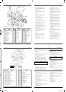
Rover Mowers Limited 7. SPARE PARTS
7.2 Handle bar spare parts
1 A03802 Handle bar-
2 A03317 Lower handle bar
3 A03583 Throttle cable- Mod. 50
3 A03326 Throttle cable- Mod. 60
4 A10016 Throttle control assembly
5 A02849 Lock handle
6 A03307 Draw bolt
7 A03500 Cable clip
8 A03518 Plug spanner
9 A10144 Grass catcher assembly
10 A03324 Mesh
11 A03447 Handle
12 A02260 Roll pin- 1/4" x 3/4"
13 A02028 Setscrew- 5/16" x 5/8" unc.W/Face.
14 A04045 Flanged nut- 5/16" unc.
15 A02223 Nyloc nut- 5/16" unc.
16 A10523 Bale assembly CE
17 A10524 Bale assembly CE
18 A10503 Handle assembly CE
19 A03739 Handle grip CE
20 A02521 Spacer CE
21 A03722 Brake cable- mod. 50,60
22 A03733 Rope stop CE
23 A02235 Nyloc nut- 1/4" unc.
24 A04083 Screw - 10 x 19mm Pan Head
25
26
27 A03622 Decal
PAGE 7
Page 3
6.1 Battery removal
1. Remove the two retaining screws from each side of the battery
support box and remove the front cover.
2. Remove the battery from the support box and simultaneously
disconnect the wiring loom from the battery terminals.
6.2 Battery installation
1. Connect the mower wiring loom to the battery with the red lead
attached to the positive (+) terminal of the battery and the black lead
to the negative (-) terminal of the battery.
2. Fit the two rubber blocks to each end of the battery and place the
battery complete with the rubber blocks into the battery support box
with the battery terminals closest to the centre of the mower.
3. Refit the battery support box front cover and retain with the two
screws.
6.3 Battery charging
A new battery when supplied with the mower may not be fully
charged to maximum capacity. The battery should have an initial
charging period of 10 to 16 hours. To charge the battery it must be
removed from the mower first.
CAUTION
Use only an approved battery charger supplied by the mower
dealer which has been designed for use with this battery.
1. Connect the battery charger to the battery with the
red lead (positive) to the positive (+) terminal of the
battery and the black (negative) lead to the negative
(-) terminal of the battery.
2. Connect the battery charger to a suitable mains
power outlet and switch on.
3. When charging is complete after 10 to 16 hours, switch off the power
outlet and disconnect the battery charger from the power outlet.
4. Disconnect the battery charger leads from the battery and refit the
battery to the mower.
6.4 Care and handling
1. Do not disassemble the battery, as it’s strong acid electrolyte may
burn your skin or clothes.
2. Do not short out the battery terminals, as this may burn the terminals
and cause damage to the equipment.
3. Do not incinerate the battery to depose of them.
The battery may explode if exposed to fire.
4. Clean the battery with a dry cloth only, never use oil, petrol, thinners
or any other petrochemical.
5. Handle the battery with care. If the battery is dropped and the case
is damaged the acid electrolyte (sulphuric acid) may leak out. Wipe
up leaking acid with a cloth and neutralise acid with an alkaline
solution.
6. In the event of electrolyte coming into contact with the skin,
immediately flush with water and seek medical attention.
5.5 Clutch lining inspection
1. Remove the spark plug lead.
2. Remove the cover plate as explained in section 5.1 “Drive chain
lubrication”.
3. Check the thickness of the friction material. Figure 13. If thickness
of the friction material is less than 1mm the clutch plate should be
replaced by an authorised Rover Mowers Limited Dealer.
5.6 Drive pawl lubrication
1. Remove the spark plug lead.
2. Support the rear wheels off the ground.
3. Remove the rear drive wheel cap (a) and the wheel plug (b). Figure
14.
4. Rotate the drive wheel to align the drive pinion with the wheel plug
hole.
5. Lubricate the slot at the centre of the drive pinion (d). Figure 15.
6. Replace the wheel plug and wheel cap.
7. Replace the spark plug lead.
5.7 Drive wheel cleaning
1. Remove the spark plug lead.
2. Support the rear wheels off the ground and remove the wheel cap.
3. Remove the ratchet plate (c) retaining the wheel to the axle.
Figure 15.
4. Remove the wheel from the axle and clean the inside of the wheel
hub.
5. Replace the wheel and retain using a new ratchet plate.
6. Replace the wheel plug and wheel cap.
7. Replace the spark plug lead.
6. MAINTENANCE - Powerstart Mowers
Rover Mowers Limited ENGLISH 5. MAINTENANCE - Self propelled mowers
Rover Mowers Limited ITALIANO 5. MANUTENDIONE
Pagina 3
5.5 Ispezione rivestimento frizione
1. Staccare il cavetto dalla candela.
2. Rimuovere la piastra di ricoprimento come spiegato in
sezione 5.1 “Lubrificazione catena trasmissione”.
3. Controllare lo spessore del rivestimento della frizione.
Figura 13. Se tale spessore e’ inferiore a 1 mm il piatto
frizione dovrebbe essere sostituito, consigliabilmente presso
il rivenditore autorizzato della Rover Mowers Limited.
5.6 Lubrificazione ingranaggio trasmissione
1. Staccare il cavetto dalla candela.
2. Rialzare da terra con un sostegno le ruote posteriori.
3. Levare il copri perno (a) e il perno (b) della ruota motrice.
Figura 14.
4. Girare la ruota motrice in modo da allineare il pignone di
trasmissione con il foro del perno della ruota.
5. Lubrificare la fessura al centro del pignone di trasmissione
(d). Figura 14.
6. Rimettere a posto il perno ed il copriperno della ruota.
7. Riattaccare il cavetto della candela.
5.7 Pulizia ruota motrice
1. Staccare il cavetto della candela.
2. Rialzare da terra le ruote posteriori e levare il copri perno
della ruota.
3. Togliere la piastrina d’arresto (c) che ferma la ruota all’asse.
Figura 15.
4. Levare la ruota dall’asse e pulirne il mozzo.
5. Nel rimettere la ruota a posto usare una piastrina d’arresto
nuova.
6. Rimettere a posto il perno e il copriruota.
7. Riattaccare il cavetto alla candela.
6.1 Rimozione batteria
1. Svitare le due viti di ritegno ai due lati della scatola
portabatteria e levarne il lato anteriore.
2. Togliere la batteria dalla scatola e nel medesimo tempo
staccare i fili dai morsetti della batteria.
6.2 Installazione batteria
1. Collegare i cavi elettrici della falciatrice alla batteria, con il
cavo rosso collegato al morsetto positivo (+) della batteria
e il cavo nero al morsetto negativo (-) della batteria.
2. Mettere i 2 pezzi di gomma ai lati estremi della batteria e
sistemare la batteria con i pezzi di gomma nella scatola
portabatteria con i morsetti in posizione piu’ vicina al centro
della falciatrice.
3. Rimettere a posto il lato anteriore della scatola portabatteria
e fissarlo con le due viti.
6.3 Caricamento batteria
Una batteria nuova, fornita insieme alla falciatrice potrebbe
alle volte non essere carica alla sua capacita’ massima.
Normalmente la batteria dovrebbe avere un periodo di carica
da 10 a 16 ore. Per caricare la batteria bisogna prima levarla
dalla falciatrice.
AVVERTENZA
Usare solo un caricabatteria approvato dalla
fabbrica e fornito dal distributore della falciatrice
perche’ si tratta di un prodotto appositamente
studiato per questo tipo di batteria.
1. Collegare il caricabatteria con la batteria: il cavo rosso
(positivo) collegato al morsetto positivo (+) della batteria ed
il cavo nero negativo al morsetto negativo (-) della batteria.
2. Collegare il caricabatteria con una presa elettrica adatta e
accendere l’interruttore.
3. Quando, dopo circa 10-16 ore si e’ completata la carica,
spegnere l’interruttore della presa elettrica e staccare la
spina del caricabatteria dalla presa elettrica.
4. Staccare i cavi del caricabatteria dalla batteria e risistemare
la batteria nel portabatteria della falciatrice.
6.4 Cura e uso
1. Non smontare la batteria in quanto l’acido dell’elettrolite
potrebbe bruciare la pelle o gli indumenti.
2. Non mettere in corto circuito i morsetti della batteria, in
quanto cio’ potrebbe bruciare i morsetti stessi e causare
danni all’equipaggiamento elettrico.
3. Non mettere la batteria nell’incineratore, nell’intento di
disfarsene. La batteria puo’ esplodere se esposta al fuoco.
4. Pulire la batteria solo con panni asciutti, non usar mai olio,
benzina, solventi o qualsiasi altro prodotto petrolchimico.
5. Maneggiare con cura la batteria. Se si fa cadere la batteria
e il contenitore si e’ danneggiato puo’ uscirne fuori dell’acido
dell’elettrolite (acido solforico). Pulire bene l’acido con un
panno e neutralizzare l’acido con una soluzione alcalina.
6. Nel caso in cui tale elettrolite venga in contatto con la pelle,
lavare subito con acqua e richiedere assistenza medica.
6. MANUTENDIONE FALCIATRICI ADIGNIZIONE
ELECTRICA
3632 Steel Export.PMD 11/19/2002, 2:46 PM8
Rover Mowers Limited ITALIANO 4. MANUTENZIONE GENERALE
Pagina 2
4.1 Filtro aria motore
Per istruzioni dettagliate sulla pulizia del filtro si prega riferirsi al
manuale rilasciato dalla fabbrica del motore.
L’elemento del filtro aria del motore deve essere pulito dopo ogni 25 ore
di falciatura normale. Se pero’ si e’ falciato in condizioni polverose
l’elemento dovra’ essere pulito piu’ frequentemente.
4.2 Filtro aria tubo aspirazione
L’elemento del filtro aria dell’aspiratore deve essere pulito dopo ogni
50 ore di falciatura normale. Se pero’ si e’ falciato in condizioni
polverose l’elemento dovra’ essere pulito piu’ frequentemente.
1. Staccare il tubo aspiratore dal portaelemento.
2. Staccare il coperchietto del portaelemento.
3. Rimuovere l’elemento filtro e batterlo gentilmente su una superfice
piatta per rimuoverne la polvere.
4. Rimettere a posto l’elemento e rimettere il coperchietto sul porta
elemento.
5. Rimettere a posto il tubo aspiratore alla base del portaelemento.
Pregasi notare che i motori "Quantum" con tubo di respirazione
d'aria lontano, non sono dotati di filtro dell'aria. Notare anche
che il filtro dell'aria in questo modello è messo sopra il motore.
AVVERTENZA
Non far entrare polvere nel tubo aspiratore aria per non
provocare danni al motore. Controllare regolarmente le
condizioni del tubo aspiratore aria e sostituirlo se
danneggiato.
4.3 Candela
Per ottenerne i migliori risultati levare la candela e controllarne le
condizioni ogni 25 ore d’uso.
1. Fermare il motore e staccare il cavetto dalla candela.
2. Pulire intorno alla candela e levare la candela.
3. Se occorre una nuova candela usare una Champion RJ19LM o
equivalente e regolare la distanza dell’elettrodo tra 0.7 e 0.8 mm.
4. Riavvitare la candela nel motore e stringere fino a 20 NM.
AVVERTENZA
Non stringere troppo la candela per non causare danni al
motore.
4.4 Apparato taglio
1. Staccare il cavetto dalla candela
2. Spostare la leva d’altezza taglio nella posizione piu’ alta.
3. Muovere la falciatrice in modo da avere la candela nella parte
superiore.
4. Ispezionare l’apparato taglio e vedere se ci sono danni o logorii.
5. Controllare i bulloni che fissano il disco. Stringere il bullone al
centro fino a 48 NM e i 3 bulloni concentrici fino a 14 NM.
6. Riportare la falciatrice in posizione normale e riattaccare il cavetto
alla candela.
AVVERTENZA
Staccare il cavetto dalla candela prima di lavorare
sull’apparato taglio.
4.5 Cambio lame
1. Staccare il cavetto dalla candela.
2. Mettere la falciatrice in posizione di taglio alto.
3. Alzare lo sportello posteriore nelle falciatrici a raccoglitore posteriore
e tenerlo aperto con l’apposito sostegno cosi’ da avere libero
accesso alle lame. Alzare le falciatrici utilitarie in modo da avere
la candela in alto.
4. Togliere le lame, i bulloni di ritegno, i dadi e le rondelle e scartare
il tutto. Lasciare solo le piastre ‘D’.
5. Mettere le lame nuove, i bulloni, le rondelle e i dadi in gruppi
completi per mantenere l’equilibrio. Figura 8.
6. Stringere i dadi delle lame fino a 16 NM. Controllare che le lame
si possano muovere liberamente quando i loro dadi sono in
tensione.
7. Rimuovere il sostegno dello sportello, riabbassare l’altezza taglio
e riattaccare il cavetto alla candela.
4.6 Controllo accelleratore
Ogni 25 ore di falciatura lubrificare la leva di controllo accelleratore con
un po’ d’olio leggero.
5. MANUTENZIONE FALCIATRICI SEMOVENTI
5.1 Lubrificazione catena trasmissione
1. Staccare il cavetto dalla candela.
2. Levare le viti (a) della piastra di ricoprimento e sollevarla (b).
Figura 9.
3. Alzare e tenere alzate con un sostegno le ruote posteriori in modo
che si possa girare liberamente la trasmissione.
4. Lubrificare con olio SAE 30 la catena di trasmissione al punto (a)
mentre si fa ruotare la catena stessa. Figura 10.
5. Rimettere a posto la piastra e fissarla con le viti.
6. Riattaccare il cavetto alla candela.
5.2 Regolazione catena trasmissione.
Catena tramissione anteriore
1. Staccare il cavetto dalla candela.
2. Rimuovere la piastra di ricoprimento.
3. Allentare il bullone del tirante (b) della catena e muovere il tirante
fino a dargli 3 mm di deviazione rispetto alla catena di trasmissione.
Figura 10.
4. Stringere il bullone del tirante e far girare le ruote motrici per
controllare se nella catena di trasmissione ci sono punti troppo tesi.
5. Rimettere a posto la piastra di ricoprimento.
Catena trasmissione posteriore
1. Staccare il cavetto dalla candela.
2. Allentare the il dado (c) del tirante della catena di trasmissione
posteriore e farlo scorrere verso l’alto in modo da tendere la catena
di trasmissione posteriore. Figura 9.
3. Stringere il dado del tirante della catena di trasmissione posteriore
e ruotare le ruote motrici per controllare se ci sono dei punti troppo
tesi.
4. Riattaccare il cavetto alla candela.
5.3 Ispezione catena trasmissione posteriore
1. Staccare il cavetto dalla candela.
2. Svitare le viti che fissano la piastra di ricoprimento dell’albero di
trasmissione (a) e levare la piastra stessa (b). Figura 11.
3. Svitare le viti di ritegno del parasassi (c) e levare il parasassi stesso.
Figura 11.
4. Svitare i dadi (d) del paracatena e far scivolar via il paracatena
stesso. Figura 12.
5. Ispezionare la catena di trasmissione e l’ingranaggio dell’asse e, se
trovato eccessivamente consumato, sostituirlo.
6. Rimettere a posto il parasassi, il paracatena e la piastra dell’albero
di trasmissione.
7. Riattaccare il cavetto alla candela.
5.4 Regolazione frizione
1. Staccare il cavetto dalla candela.
2. Allentare il dado di fissaggio (a) e girare il registro (b) in senso
orario fino a che la frizione faccia attrito. Figura 13.
3. Rigirare indietro in senso antiorario il registro per 2 o 3 giri e
stringere il dado di fissaggio.
4. Riattaccare il cavetto alla candela.
Rover Mowers Limited DEUTSCH VORWORT
Verehrter Kunde,
Wir bedanken uns, daß Sie ein Rover Produkt gekauft haben. Alle Rover-Rasenmäher sind entworfen und konstruiert, optimales
Grasschneiden unter normalen Grasschneideverhältnissen zu gewährleisten.
Diese Gebrauchsanweisung erklärt die Inbetriebnahme und Wartung des Rover Mähers. Beachten Sie bitte vor Inbetriebnahme die Hinweise
in der Gebrauchsanweisung.
Sollte etwas unklar sein, verständigen Sie bitte Rover Mowers Limited oder einen ortszuständigen Beauftragten des Rover Kundendienstes.
Rover Mowers Limited behält sich das Recht vor, Änderungen und Verbesserungen zu jeder Zeit, ohne Ankündigung und unverbindlich,
an ihrem Produkt vorzunehmen. Die Firma behält auch das Recht vor, die Herstellung irgendwelchen Produktes nach eigenem Ermessen
zu jeder Zeit einzustellen.
Um besondere Information zu betonen, werden die Wörter VORSICHT und ACHTUNG benützt.
VORSICHT
Sorgen Sie für die Sicherheit des Bedieners und Dritten im
Arbeitsbereich des Gerätes. Sicherheitsmaßnahmen müssen
beachtet werden, um Unfälle zu verhindern.
INHALT ........................................................................ SEITE
Vorwort ................................................................................iii
Sicherheitshinweise ................................................................. iv
1. Montage............................................................................. 1
1.1 Grasfangvorrichtung ................................................ 1
2. Vor Inbetriebnahme........................................................... 1
2.1 Klappgriffbügel ....................................................... 1
2.2 Griffhöhe ................................................................. 1
2.3 Ölen des Motors....................................................... 1
2.4 Benzin ...................................................................... 1
2.5 Bedienung ................................................................ 1
3. Inbetriebnahme.................................................................. 1
3.1 Grasfangvorrichtung ................................................ 1
3.2 Schnitthöhe einstellen.............................................. 1
3.3 Anlassen des Motors................................................ 1
3.4 Abstellen des Motors ............................................... 1
3.5 Selbstangetriebene Mäher........................................ 1
3.6 Messerbremeuug ...................................................... 1
4. Allgemeine Wartung ......................................................... 2
4.1 Motorluftreiniger ..................................................... 2
4.2 Schnorchelluftfiten .................................................. 2
4.3 Zündkerze ................................................................ 2
4.4 Schneidwerkzeug ..................................................... 2
4.5 Messerwechsel ......................................................... 2
4.6 Gashebelkontrolle .................................................... 2
5. Wartung für selbstangetriebene Mäher ........................ .... 2
5.1 Ölen der Antriebskette ............................................. 2
5.2 Einstellung der Antriebskette ................................. 2
5.3 Kontrolle der hinteren Antriebskette ....................... 2
5.4 Einstellung der Kupplung ........................................ 2
5.5 Kontrolle des Kupplungsbelages ............................. 3
5.6 Ölen der Antriebssperrklinke................................... 3
5.7 Reinigung des Antriebsrades ................................... 4
ACHTUNG
Folgen Sie diesen Hinweisen, um Schaden am Mäher und
eventuelle Ungültigkeit der Garantie zu vermeiden.
6. Wartung für Powerstart Mäher
6.1 Entfernung der Batterie. .......................................... 3
6.2 Einbau der Batterie .................................................. 3
6.3 Batterieaufladung..................................................... 3
6.4 Pflege und Umgang ................................................. 3
7. Technische Daten ............................................................. 4
7.1 Bescheinigung der Übereinstimmung .................. 4,5
8. Ersatzteile .......................................................................... 6
8.1 Serie 85000, 86000, 96000 Mäher ........................... 6
8.2 Serie 85000, 86000, 96000 Griffbügel .................... 7
8.3 Selbstangetriebener Mäher ...................................... 8
8.4 Powerstart Mäher ..................................................... 9
ABBILDUNGEN ............................................................ SEITE
Abb. 1. Grasfangvorrichtung............................................... i
Abb. 2. Griffhöhe Einstellung .............................................i
Abb. 3. Gasmarkierung ....................................................... i
Abb. 4. Bedieneranwesenheitakontrolle ............................. i
Abb. 5. Selbstantriebmarkierung ........................................ i
Abb. 6. Einhängen der Fangvorrichtung ............................. i
Abb. 7. Schnitthöhe Einstellung ......................................... i
Abb. 8. Messerbolzenmontage ............................................ i
Abb. 9. Antriebsketten Abdeckplatte .................................ii
Abb. 10. Antriebsketten .......................................................ii
Abb. 11. Antriebswellen Abdeckplatte ................................ ii
Abb.12. Steinschutzvorrichtung.......................................... ii
Abb.13. Kupplungeinstellung ............................................. ii
Abb.14. Antriebsrad ............................................................ii
Abb.15. Antriebsritzel......................................................... ii
Abb.16.
Powerstart bedienung .....................................
ii
iii
Rover Mowers Limited ITALIANO SICUREZZA
iv
ISTRUZIONI SULLA SICUREZZA
1. Come addestrarsi
a. Leggere attentamente le istruzioni. Familiarizzarsi con i comandi
per il giusto uso della macchina.
b. Non permettere mai ai bambini o a persone non al corrente con
queste istruzioni di usare la falciatrice. Tenere presente che ci
possono essere delle leggi locali che riguardano l’eta’ minima
dell’operatore della falciatrice.
c. Non usare mai la falciatrice mentre ci sono bambini, persone, o
anche animali di casa nelle vicinanze.
d. Tenere presente che l’operatore o utente e’ ritenuto responsabile
degli incidenti o dei rischi o pericoli causati a terzi o a proprieta’
di terzi.
2. Preparativi
a. Ricordarsi di vestire calzature pesanti e pantaloni lunghi quando si
usa la falciatrice. Non si deve usare la falciatrice se si e’ a piedi nudi
o si calzano sandali.
b. Ispezionare bene l’area da falciare e togliere tutti i sassi, bastoncini,
fili metallici, ossa ed altri oggetti estranei.
c. Attenzione - La benzina e’ molto infiammabile
Usare le seguenti precauzioni:
i. Tenere il carburante negli appositi contenitori.
ii. Fare il pieni del serbatoio all’aperto e non fumare mentre si
fa il pieno.
iii. Fare il pieno prima di accendere il motore. Non togliere il
tappo del serbatoio o aggiungere benzina con il motore in
moto o quando il motore e’ ancora caldo.
iv. Se si e’ sparsa della benzina non accendere il motore; allontanare
invece la falciatrice dall’area bagnata di benzina ed evitare di creare
scintille, fino a quando la benzina si sia evaporata.
v. Rimettere al suo posto e stringere bene sia il tappo del serbatoio
che quello del contenitore.
d. Sostituire i silenziatori difettosi.
e. Prima di iniziarne l’uso ispezionare sempre le lame, i bulloni delle
lame e tutto l’apparato da taglio ed accertarsi che non siano logorati
o danneggiati. Se ci sono lame danneggiate o logorate sostituire le
lame al completo per mantenere l’equilibrio.
f. Nelle falciatrici multilame fare attenzione a non far torcere una
lama perche’ cio’ puo’ causare la torcitura di altre lame.
3. Messa in funzione
a. Non mettere in moto il motore in uno spazio ristretto dove il fumo
di scappamento con gas ossido di carbonio possa addensarsi.
b. Usare la falciatrice solo di giorno oppure con luce artificiale
intensa.
c. Evitare se possibile di usare la falciatrice su erba bagnata.
d. Sui pendii stare attenti a dove mettere i piedi.
e. Camminare, non correre mai.
f. Usando falciatrici semoventi, falciare i pendii trasversalmente,
mai andando in giu’ o in su’.
g. Stare molto attenti nei cambiamenti di direzione sui pendii.
h. Non falciare pendii troppo ripidi.
i. Esercitare la massima precauzione nelle inversioni di marcia o nel
tirare la falciatrice verso se stessi.
j. Assicurarsi che la lama o le lame siano fermate, se si deve alzare
la falciatrice per portarla su superfici non erbose oppure verso o
dall’area che deve essere falciata.
k. Non usare mai la falciatrice che abbia i pannelli di protezione o i
paraurti difettosi, oppure non abbia perfettamente a posto quegli
apparati di sicurezza come i deflettori o/e i raccoglitori d’erba.
l. Non cambiare la posizione di registrazione del regolatore del
motore e non sovraccellerare il motore.
m. Liberare tutte le lame e staccare le frizioni di trasmissione prima
di accendere il motore.
n. Accendere il motore o mettere in funzione la falciatrice con molta
precauzione, seguendo le istruzioni e tenendo i piedi ben distanti
dalle lame.
o. Non alzare la falciatrice quando si deve metterla in moto o
accendere il motore. A meno che la falciatrice debba essere alzata
per essere messa in moto: nel qual caso non deve essere alzata piu’
del necessario e soltanto dalla parte piu’ lontana dall’operatore.
p. Non accendere il motore stando davanti allo scarico erba.
q. Non mettere le mani o i piedi vicini o sotto le parti ruotanti. Stare
sempre lontani dall’apertura dello scarico.
r. Non sollevare o trasportare mai una falciatrice con motore acceso.
s. Spegnere il motore e staccare il cavetto dalla candela:
i. Prima di levare delle ostruzioni o sbloccare lo scarico.
ii. Prima di controllare, pulire, od eseguire lavori sulla falciatrice.
iii. Dopo aver incontrato un oggetto estraneo. Ispezionare la
falciatrice per accertarsi dei danni. Riparare i danni prima di
ricominciare a falciare.
iv. Se la falciatrice comincia a vibrare in maniera anomala,
controllare immediatamente.
t. Spegnere il motore:
i. Ogni volta che bisogna allontanarsi dalla falciatrice.
ii. Prima di aggiungere o fare il pieno di benzina.
u. Ridurre l’accellerazione durante i periodi di corsa a vuoto del
motore e, se il motore possiede una valvola di chiusura, chiudere
il flusso del carburante alla conclusione della falciatura.
4. Manutenzione e immagazzinaggio.
a. Assicurarsi che tutti i bulloni, viti e dadi siano stretti, in modo che
tutto l’apparato sia in condizioni d’uso sicure.
b. Non mettere o lasciare la falciatrice con del carburante nel
serbatoio in un posto in cui i vapori di benzina possano raggiungere
delle fiamme vive o delle scintille.
c. Far raffreddare il motore prima di mettere la falciatrice nel suo
ripostiglio.
d. Allo scopo di ridurre il rischio d’incendio, levare erba, foglie o
ingrassaggio superfluo dalle superfici vicine al motore, silenziatore,
batteria e serbatoio.
e. Ispezionare spesso il raccoglitore erba per vedere se ci sono
deterioramenti o logorii.
f. Per ragioni di sicurezza sostituire le parti o i pezzi danneggiati o
logorati.
g. Se il serbatoio del carburante deve essere svuotato, svuotarlo
all’aperto.
Rover Mowers Limited DEUTSCH 1. MONTAGE
Seite 1
1.1 Grasfangvorrichtung
1. Den Griff der Fangvorrichtung lokallsleren und seine vordere
Haltevorrichtungen und die sich oben auf der Fangvorrichtung
befindenden Spalten aufeinander ausrichten und fest elsetzen. Abb1.
2. Fest auf das Oberteil drücken um die Haken in die Spalten
einzusetzen. Abb.2.
3. Mit den zwei beigelegien befestigen.
2. VOR INBETRIEBNAHME
2.1 Klappgriffbügel
1. Griffknaufen: Diese Knaufen drehen, um den Griffbügel in
Mähstellung zu setzen oder zum Zusammenklappen für Lagerung.
2. Schließhebel: Den Hebel anheben, um den Griffbügel zu lösen.
Den Schließhebel nach unten drücken, um den Griffbügel in
Mähstellung zu setzen. Die Gegenmutter mit einem 1/2" AF
Schlüssel anziehen, um die Spannung einzustellen.
2.2 Griffhöhe
1. Die zwei Muttern (A) unten am Griffbügel auf beiden Seiten des
Mähers mit einem 1/2" AF Schlüssel lockern. Abb.2.
2. Den Griffbügel auf die gewünschte Höhe einstellen und die
Muttern fest anziehen.
2.3 Ölen des Motors
Den Ölstand immer vor Anlassen des Motors prüfen. Lesen Sie die
Anweisungen des Motor Herstellers.
1. Den Mäher auf eine ebene Fläche stellen und um den Ölmeßstab
oder den Ölstopfen herum reinigen.
2. Den Ölmeßstab oder Ölstopfen her ausziehen.
3. Öl langsam miteinem Trichter vorschriftsmäßig einfüllen.
4. Um den Ölstand zu prüfen, den Meßstab oder Ölstopfen wieder
einsetzen.
ACHTUNG
Um vorzeitigen Motorausfall zu vermeiden, einen sauberen
Trichter benützen und mögliche Schmutzstoffe abwischen.
2.4 Benzin
1. Den Mäher auf eine ebene Fläche, die gut belüftet ist, stellen und
um den Tankdeckel herum abwischen.
2. Den Tank mit bleifreiem Benzin durch einen sauberen Trichter
füllen.
3. Den Deckel wieder aufsetzen und verschüttetes Benzin abwischen.
2.5 Bodionung
Gasbedienung
Markierung A (aus)
(langsam) (schnell). Bild. 3.
Bedieneranwesenheitakontrolle
Giff in Richtung Giffbügel vorgestzt (I), Motor und messer rotieren frei,
Griff gelôst (O) Motor und messer stoppen. Abb 4.
Selbetantriebbetätgung
Einstellung auf E (ein) aktiviert die Kupplung und den Motor vorwärts.
Einstellung auf A (aus) schaltet die Kupplung aus und bringt den Mäher
zum Stehen. Bild. 5.
Powerstart Kontrollen
Zundschlüssel auf Stelle an (I) drehen, um den Anlasser einzuschalten.
Beim Anspringen des Motors den Schlück lassen. Abb14.
3. INBETRIEBNAHME
3.1 Grasfangvorrichtung
Einhängen der Grasfangvorrichtung
1. Die hintere Klappe des Mähers anheben.
2. Den Griff an der Fangvorrichtung festhalten und die Vorrichtung
hinten am Mäher anbringen. Abb.6.
3. Die hintere Klappe senken, sodaß die Rückkante der Klappe sich
über die Fangvorrichtung einhakt
Abnehmen der Grasfangvorrichtung
1. Den oberen Griff an der Fangvorrichtung festhalten und anheben.
2. Die hintere Klappe des Mähers mit der Grasfangvorrichtung
anheben, um diese loszulassen.
3. Die Grasfangvorrichtung vom Mäher entfernen und die hintere
Klappe senken.
3.2 Schnitthöhe einstellen
1. Den Hebel (A) nach außen ziehen, um ihn auszurasten.(B). Abb.7.
2. Den Hebel nach außen gedrückt, auf die gewünschte Schnitthöhe
einstellen, dann den Hebel wieder einrasten lassen.
3.3 Anlassen des Motors
1. Gashebel auf Schnell stellen.
2. Den Ansaugbalg 5 Mal fest drücken.
3. Den 'Bedieneranwesen heits kontrollegriff' festhatten und gegen
den Friffbügel drücken. Lesen Sie die Anweisungen des Motor
herstellers.
4. Anlassergriff festhalten und ausziehen, oder beim Powerstart
Mäher den Zündschlüssel drehen.
5. Nach Anlauf des Motors Gashebel auf Landsam stellen.
ACHTUNG
Wenn der Motor beim Powerstart Mäher nach 3 Sekunden
ständigen Ankurbelns nicht anspringt, den Schlüssel loslassen, 10
Sekunden abwarten, und den Motor dann erneut anlassen. Springt
der Motor immer noch nicht an, den Benzinstand, Batterieanschlüsse
und die Batterie überprüfen. Langsames Kurbeln weist auf eine
schlechtgeladene Batterie. Die Batterie aufladen!
Lesen Sie Abschnitt 6.3 unter Batterieaufladung.
3.4 Abstellen des Motors
1. Den Gashebel auf Stop einstellen.
2. Den Benzinhahn, wenn vorhanden, zudrehen.
3. Beim Powerstart Mäher den Zündschlüssel abziehen.
3.5 Einstellung der Kupplung für selbstangetriebene Mäher
1. Den Motor anlassen und die Drehzahl auf die gewünschte
Schneidgeschwindigkeit einstellen.
2. Kupplungshebel nach vorne drücken, um den Selbstantrieb der
hinteren Räder einzusetzen.
3. Zum Aussetzen der Selbstantriebräder, den Kupplungshebel
loslassen.
ACHTUNG
Der Kupplungshebel darf auf keinen Fall nur halb im Eingriff
stehen, denn dies führt zu übermäßigem Verschleiß der
Kupplung.
3.6 Messerbremsung
Der Mäher ist mit einer Messerbremsung ausgestattet. Wenn die
bedienerkontrolle an die Lenkstabnge gedrückt wird, ist die
Bremae ausgeschaltet. (A). Wenn die bedienerkontrolle gelöst
wird, ist die Bremse eingeschaltet (E). Bild__
3632 Imposed PDF's.indd 4 18/05/2006 2:36:12 PM