


-
16
-
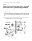
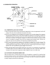
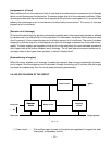
5-3 GENERATOR OPERATION
5-3-1 GENERATION of NO-LOAD VOLTAGE
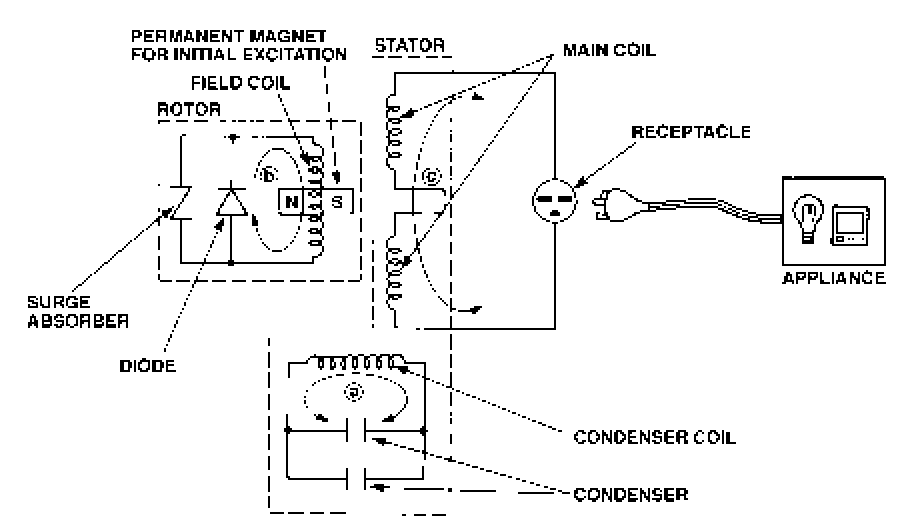
(1) When the generator starts running, the permanent magnet built-in to the rotor generates 3 to 6V of AC
voltage in the main coil and condenser coil wound on the stator.
(2) As one or two condensers are connected to the condenser coil, the small voltage at the condenser
coil generates a minute current a which flows through the condenser coil. At this time, a small flux is
produced with which the magnetic force at the rotor’s magnetic pole is intensified. When this mag-
netic force is intensified, the respective voltages in the main coil and condenser coil rise up. As the
current a increases, the magnetic flux at the rotor’s magnetic pole increases further. Thus the volt-
ages at the main coil and condenser coil keep rising by repeating this process.
(3) As AC current flows through the condenser coil, the density of magnetic flux in the rotor changes. This
change of magnetic flux induces AC voltage in the field coil, and the diode rectifier in the field coil
circuit rectifies this AC voltage into DC. Thus a DC current b flows through the field coil and magne-
tizes the rotor core to generate an output voltage in the main coil.
(4) When generator speed reaches 3000 to 3300 rpm, the current in the condenser coil and field coil
increases rapidly. This acts to stabilize the output voltage of each coils. If generator speed further
increases to the rated value, the generator output voltage will reach to the rated value.
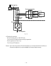
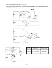
5-3-2 VOLTAGE FLUCTUATIONS UNDER LOAD
When the output current c flows through the main coil to the appliance, a magnetic flux is produced and
serves to increase current a in the condenser coil. When current a increases, the density of magnetic
flux across the rotor core rises. As a result, the current flowing in the field coil increases and the genera-
tor output voltage is prevented from decreasing.
Fig. 5-11