


7-6
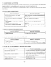
ELECTRIC APPARATUS (Electric Starter)
1.
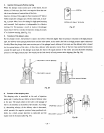
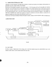
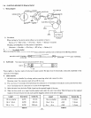
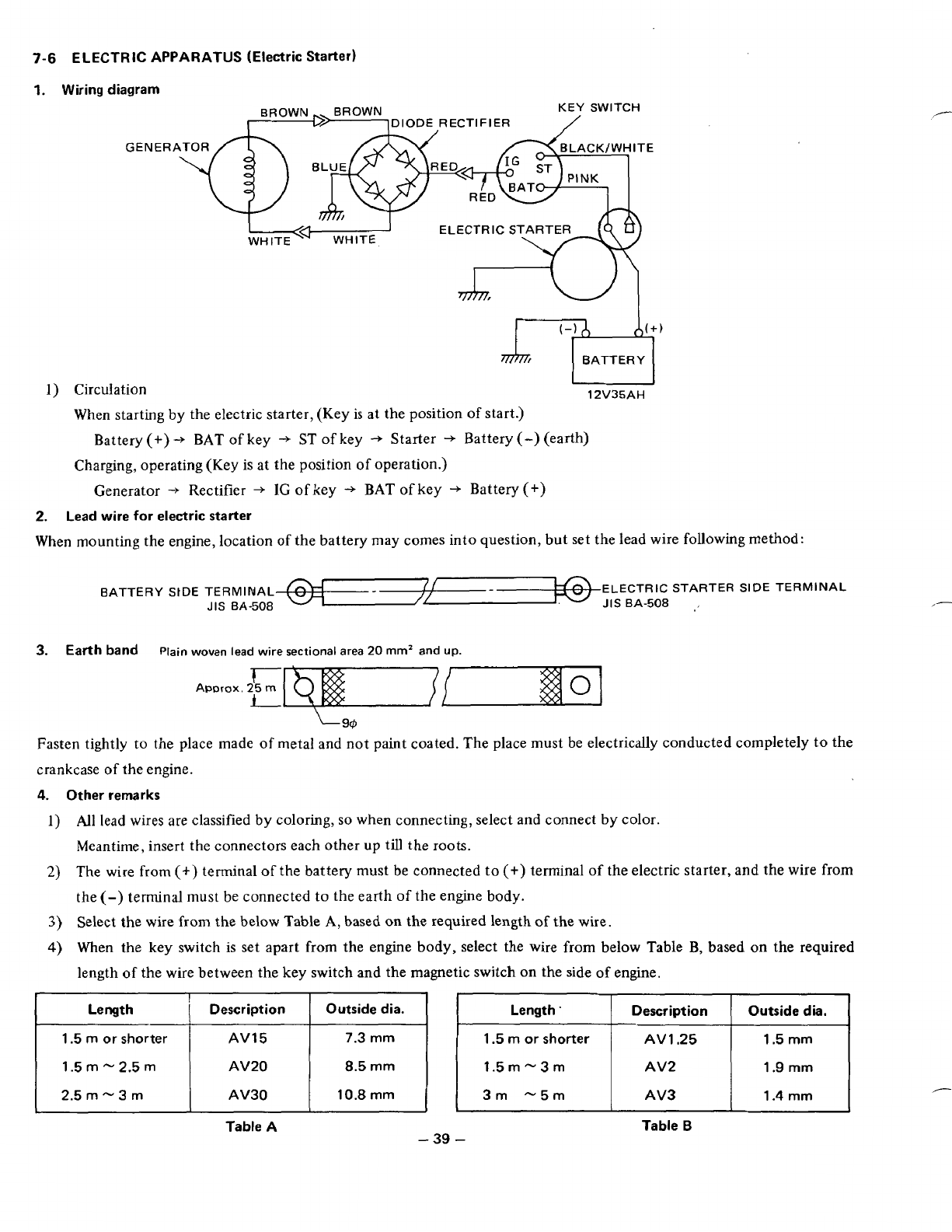
Wiring diagram
KEY SWITCH
GENERATOR
ELECTRIC STARTE
1)
Circulation
12V35AH
When starting by the electric starter, (Key is at the position
of
start.)
Battery
(+)
-+
BAT
of
key
+
ST
of
key
+
Starter
+
Battery
(-)
(earth)
Charging, operating (Key is
at
the position
of
operation.)
Generator
"f
Rectifier
+
IC
of
key
+.
BAT
of
key
+.
Battery
(+)
2.
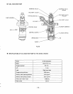
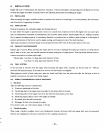
Lead wire
for
electric starter
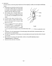
When mounting the engine, location of the battery may comes into question, but set the lead wire following method:
BATTERY
StDE
TERMINAL ELECTRIC STARTER
SIDE
TERMINAL
JIS
BA-508
JIS
BA-508
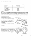
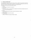
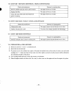
3.
Earth band
Plain woven
lead
wire
sectional
area
20
mm2
and
up.
I"
L
Approx.
25
Fasten tightly
to
the place made
of
metal and not paint coated. The place must be electrically conducted completely to the
crankcase
of
the engine.
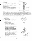
4,
Other remarks
1)
All
lead wires are classified by coloring,
so
when connecting, select and connect by color.
Meantime, insert the connectors each other up till the
roots.
2)
The wire
from
(+)
terminal
of
the battery must be connected to
(+)
terminal
of
the electric starter, and the wire from
the
(-)
terminal must be connected to the earth
of
the engme body.
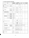
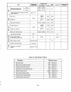
3)
Select the wire
from
the below Table
A,
based
on
the required length
of
the wire.
4)
When the key switch is set apart from the engine body, select the wire
from
below Table B, based on the required
length
of
the wire between the key switch and the magnetic switch
on
the side
of
engine.
I
Length
Outside dia.
Description
Length.
Outside dia.
Description
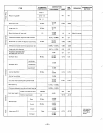
1.5
m
or shorter
1.4
mm AV3
3m "5m
10.8 mm
AV30
2.5
m
-
3
m
1.9
mm
AV2
'i.5m-31-17
8.5
mm AV20 1.5
m
-
2.5
m
1.5
mm AV
1
-25
1.5
m
or
shorter
7.3
mm
AV15
Table A Table
B
-39
-
I-
,"-